


Chapter 4 Signal Connections
6023E/6024E/6025E User Manual 4-42 ni.com
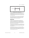
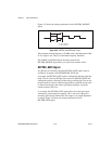
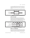
As an output, the UPDATE* signal reflects the actual update pulse that is
connected to the DACs. This is true even if the updates are externally
generated by another PFI. The output is an active low pulse with a pulse
width of 300 to 350 ns. This output is set to high impedance at startup.
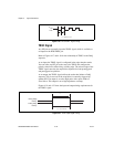
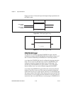
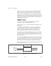
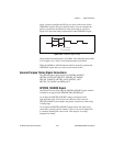
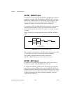
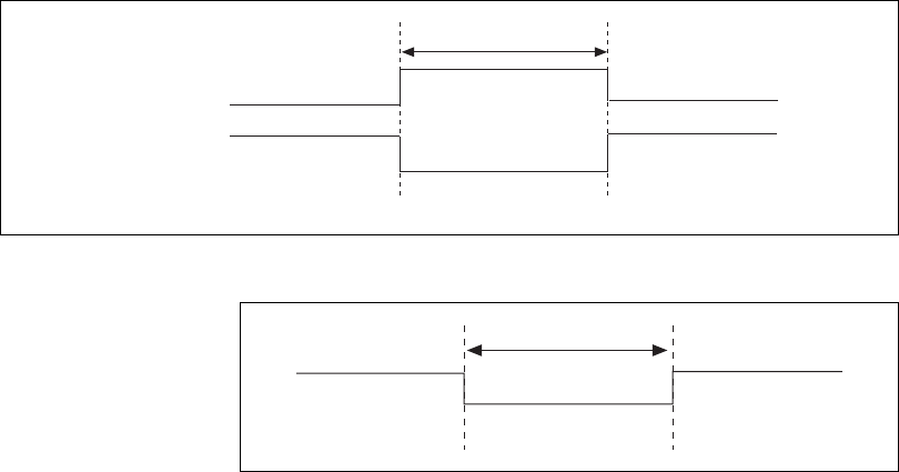
Figures 4-32 and 4-33 show the input and output timing requirements for
the UPDATE* signal.
Figure 4-32. UPDATE* Input Signal Timing
Figure 4-33. UPDATE* Output Signal Timing
The DACs are updated within 100 ns of the leading edge. Separate the
UPDATE* pulses withenough time thatnew datacan be writtento the DAC
latches.
The device UI counter normally generates the UPDATE* signal unless you
select some external source. The UI counter is started by the WFTRIG
signal and can be stopped by software or the internal Buffer Counter.
D/A conversions generated by either an internal or external UPDATE*
signal do not occur when gated by the software command register gate.
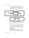
UISOURCE Signal
Any PFI pin can externally input the UISOURCE signal, which is not
available as an output on the I/O connector. The UI counter uses the
UISOURCE signal as a clock to time the generation of the UPDATE*
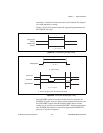
Rising-Edge
Polarity
Falling-Edge
Polarity
t
w
t
w
= 10 ns minimum
t
w
t
w
= 300-350 ns