


Chapter 4 Signal Connections
6023E/6024E/6025E User Manual 4-38 ni.com
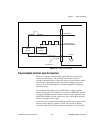
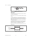
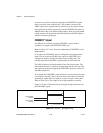
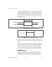
A counter on your device internally generates the STARTSCAN signal
unless you select some external source. This counter is started by the
TRIG1 signal and is stopped either by software or by the sample counter.
Scans generated by either an internal or external STARTSCAN signal are
inhibited unless they occur within aDAQsequence. Scans occurring within
a DAQ sequence can be gated by either the hardware (AIGATE) signal or
software command register gate.
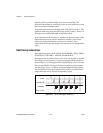
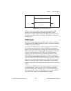
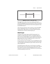
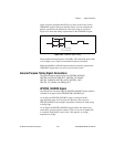
CONVERT* Signal
Any PFI pin can externally input the CONVERT* signal, which is
available as an output on the PFI2/CONVERT* pin.
Refer to Figures 4-17 and 4-18 for the relationship of CONVERT* to the
DAQ sequence.
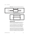
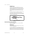
As an input, the CONVERT* signal is configured in the edge-detection
mode. You can select any PFI pin as the source for CONVERT* and
configure the polarity selection for either rising or falling edge. The
selected edge of the CONVERT* signal initiates an A/D conversion.
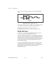
The ADC switches to hold mode within 60 ns of the selected edge. This
hold-mode delay time is a function of temperature and does not vary from
one conversion to the next. Separate the CONVERT* pulses by at least 5 µs
(200 kHz sample rate).
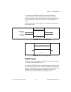
As an output, the CONVERT* signal reflects the actual convert pulse that
is connected to the ADC. This is true even if the conversions are externally
generated by another PFI. The output is an active low pulse with a pulse
width of 50 to 150 ns. This output is set to high impedance at startup.
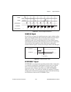
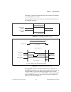
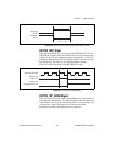
Figures 4-27 and 4-28 show the input and output timing requirements for
the CONVERT* signal.
Figure 4-27. CONVERT* Input Signal Timing
Rising-Edge
Polarity
Falling-Edge
Polarity
t
w
t
w
= 10 ns minimum