


Chapter 3 Hardware Overview
6023E/6024E/6025E User Manual 3-2 ni.com
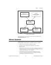
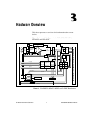
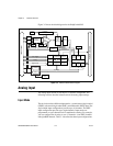
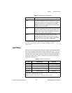
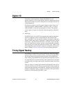
Figure 3-2 shows the block diagram for the DAQCard-6024E.
Figure 3-2. DAQCard-6024E Block Diagram
Analog Input
The analog input section of each device is software configurable. The
following sections describe in detail each of the analog input settings.
Input Mode
Thedevices havethree differentinputmodes—nonreferenced single-ended
(NRSE), referencedsingle-ended (RSE), and differential (DIFF) input.The
single-ended input configurations provide up to 16 channels. The DIFF
input configuration provides up to eight channels. Input modes are
programmed on a per channel basis for multimode scanning. For example,
you can configure the circuitry to scan 12 channels—four DIFF channels
and eight RSEchannels. Table 3-1 describes the three input configurations.
I/O Connector
3
PCMCIA Connector
12-Bit
Sampling
A/D
Converter
NI-PGIA
Gain
Amplifier
Calibration
Mux
Mux Mode
Selection
Switches
Analog
Muxes
Voltage
REF
Calibration
DACs
Dither
Circuitry
DAQ - STC
Analog Input
Timing/Control
Analog Output
Timing/Control
Digital I/O
Trigger
Counter/
Timing I/O
RTSI Bus
Interface
Interrupt
Request
Bus
Interface
(8)
(8)
AI Control
Data (16)
Analog
Input
Control
EEPROM
Control
DAQ-PCMCIA
DAQ-STC
Bus
Interface
Analog
Output
Control
Bus
Interface
IRQ
ADC
FIFO
EEPROM
6
Calibration
DACs
DAC0
DAC1
AO Control
Configuration
Memory
PFI / Trigger
Timing
Digital I/O (8)
+
–