


Chapter 4 Signal Connections
© National Instruments Corporation 4-23 6023E/6024E/6025E User Manual
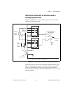
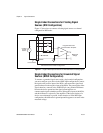
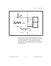
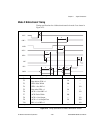
TTL signals and driving external devices such as the LED shown in
Figure 4-11.
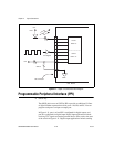
Port C Pin Assignments
♦ 6025 only
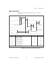
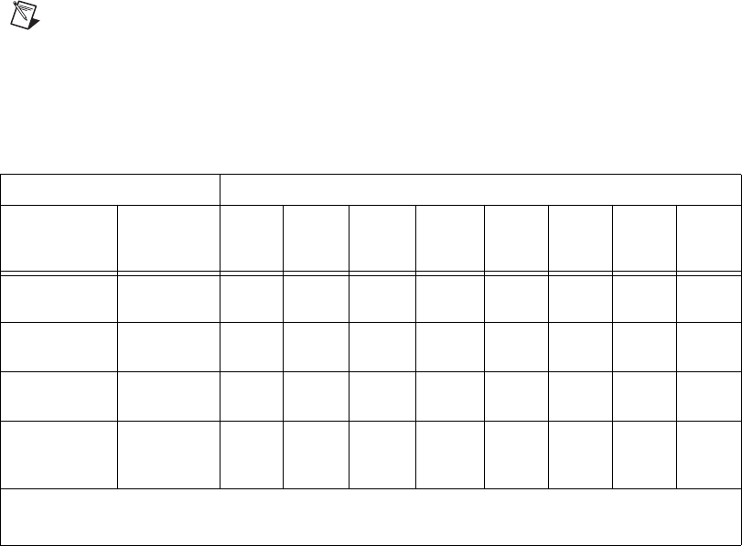
The signals assigned to port C depend on how the 82C55A is configured.
In mode 0, or no handshaking configuration, port C is configured as two
4-bit I/O ports. In modes 1 and 2, or handshaking configuration, port C
is used for status and handshaking signals with any leftover lines available
for general-purpose I/O. Table 4-4 summarizes the port C signal
assignments for each configuration. You can also use ports A and B in
different modes; the table does not show every possible combination.
Note
Table 4-4 shows both the port C signal assignments and the terminology
correlation between different documentation sources. The 82C55A terminology refers
to the different 82C55A configurations as modes, whereas NI-DAQ, ComponentWorks,
LabWindows/CVI, and LabVIEW documentation refers to them as handshaking and no
handshaking.
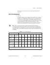
Table 4-4. Port C Signal Assignments
Configuration Terminology Signal Assignments
6023E/
6024E/6025E
User Manual
National
Instruments
Software
PC7 PC6 PC5 PC4 PC3 PC2 PC1 PC0
Mode 0
(Basic I/O)
No
Handshaking
I/O I/O I/O I/O I/O I/O I/O I/O
Mode 1
(Strobed Input)
Handshaking
I/O I/O IBF
A
STB
A
* INTR
A
STB
B
* IBFB
B
INTR
B
Mode 1
(Strobed Output)
Handshaking
OBF
A
* ACK
A
* I/O I/O INTR
A
ACK
B
* OBF
B
* INTR
B
Mode 2
(Bidirectional
Bus)
Handshaking
OBF
A
* ACK
A
* IBF
A
STB
A
* INTR
A
I/O I/O I/O
* Indicates that the signal is active low.
Subscripts A and B denote port A or port B handshaking signals.