


© National Instruments Corporation 1-1 6023E/6024E/6025E User Manual
1
Introduction
This chapter describes the 6023E, 6024E, and 6025E devices, lists what
you need to get started, gives unpacking instructions, and describes the
optional software and equipment.
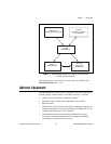
Features of the 6023E, 6024E, and 6025E
The 6025E features 16 channels (eight differential) of analog input,
two channels of analog output, a 100-pin connector, and 32 lines of digital
I/O. The 6024E features 16 channels of analog input, two channels of
analog output, a 68-pin connector and eight lines of digital I/O. The 6023E
is identical to the 6024E, except that it does not have analog output
channels.
These devices use the National Instruments DAQ-STC system timing
controller for time-related functions. The DAQ-STC consists of three
timing groups thatcontrol analog input, analogoutput, and general-purpose
counter/timer functions. These groups include a total of seven 24-bit and
three 16-bit counters and a maximum timing resolution of 50 ns. The
DAQ-STC makes possible such applications as buffered pulse generation,
equivalent time sampling, and seamless changing of the sampling rate.
♦ PCI-6023E, PCI-6024E, PCI-6025E, and PXI-6025E only
With many DAQ devices, you cannot easily synchronize several
measurement functions to a common trigger or timing event. These devices
have the Real-Time System Integration (RTSI) bus tosolve this problem. In
a PCI system, the RTSI bus consists of the National Instruments RTSI bus
interface and a ribbon cable to route timing and trigger signals between
several functions on as many as five DAQ devices in your computer. In a
PXI system, the RTSI bus consists of the National Instruments RTSI bus
interface and the PXI trigger signals on the PXI backplane to route timing
and trigger signals between several functions on as many as seven DAQ
devices in your system.