


Chapter 4 Signal Connections
6023E/6024E/6025E User Manual 4-34 ni.com
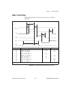
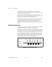
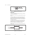
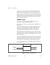
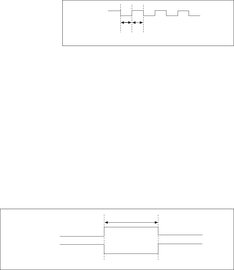
Figure 4-20. EXTSTROBE* Signal Timing
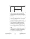
TRIG1 Signal
Any PFI pin can externally input the TRIG1 signal, which is available as
an output on the PFI0/TRIG1 pin.
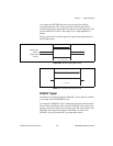
Refer to Figures 4-17 and 4-18 for the relationship of TRIG1 to the DAQ
sequence.
As an input, the TRIG1 signal is configured in the edge-detection mode.
You can select any PFI pin as the source for TRIG1 and configure the
polarity selection for either rising or falling edge. The selected edge of the
TRIG1 signal starts the data acquisition sequence for both posttriggered
and pretriggered acquisitions.
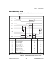
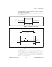
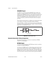
As an output, the TRIG1 signal reflects the action that initiates a DAQ
sequence. This is true even if the acquisition is externally triggered by
another PFI. The output is an active high pulse with a pulse width of
50 to 100 ns. This output is set to high impedance at startup.
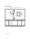
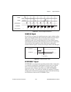
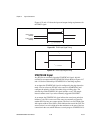
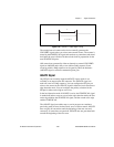
Figures 4-21 and 4-22 show the input and output timing requirements for
the TRIG1 signal.
Figure 4-21. TRIG1 Input Signal Timing
t
w
t
w
V
OH
V
OL
t
w
= 600 ns or 5
µ
s
Rising-Edge
Polarity
Falling-Edge
Polarity
t
w
t
w
= 10 ns minimum