


Chapter 4 Signal Connections
6023E/6024E/6025E User Manual 4-8 ni.com
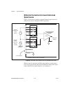
Analog Input Signal Overview
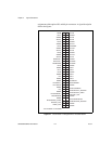
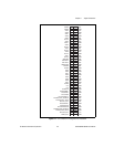
The analog input signals for these devices are ACH<0..15>, ASENSE, and
AIGND. Connection of these analog input signals to your device depends
on the type of input signal source and the configuration of the analog input
channels you are using. This section provides an overview of the different
types of signal sources and analog input configuration modes. More
specific signal connection information is provided in the Analog Input
Signal Connections section.
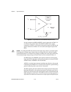
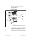
Types of Signal Sources
When configuring the input channels and making signal connections,
you must first determine whether the signal sources are floating or
ground-referenced.
PFI4/GPCTR1_GATE DIO — V
cc
+0.5 3.5 at (V
cc
-0.4) 5at0.4 1.5 50 kΩ pu
GPCTR1_OUT DO — — 3.5 at (V
cc
-0.4) 5at0.4 1.5 50 kΩ pu
PFI5/UPDATE* DIO — V
cc
+0.5 3.5 at (V
cc
-0.4) 5at0.4 1.5 50 kΩ pu
PFI6/WFTRIG DIO — V
cc
+0.5 3.5 at (V
cc
-0.4) 5at0.4 1.5 50 kΩ pu
PFI7/STARTSCAN DIO — V
cc
+0.5 3.5 at (V
cc
-0.4) 5at0.4 1.5 50 kΩ pu
PFI8/GPCTR0_SOURCE DIO — V
cc
+0.5 3.5 at (V
cc
-0.4) 5at0.4 1.5 50 kΩ pu
PFI9/GPCTR0_GATE DIO — V
cc
+0.5 3.5 at (V
cc
-0.4) 5at0.4 1.5 50 kΩ pu
GPCTR0_OUT DO — — 3.5 at (V
cc
-0.4) 5at0.4 1.5 50 kΩ pu
FREQ_OUT DO — — 3.5 at (V
cc
-0.4) 5at0.4 1.5 50 kΩ pu
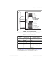
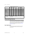
AI = Analog Input DIO = Digital Input/Output pu = pullup
AO = Analog Output DO = Digital Output
Note: The tolerance on the 50 kΩ pullup and pulldown resistors is very large. Actual value can range between 17 kΩ and
100 kΩ.
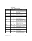
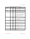
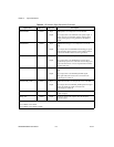
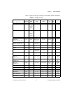
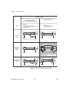
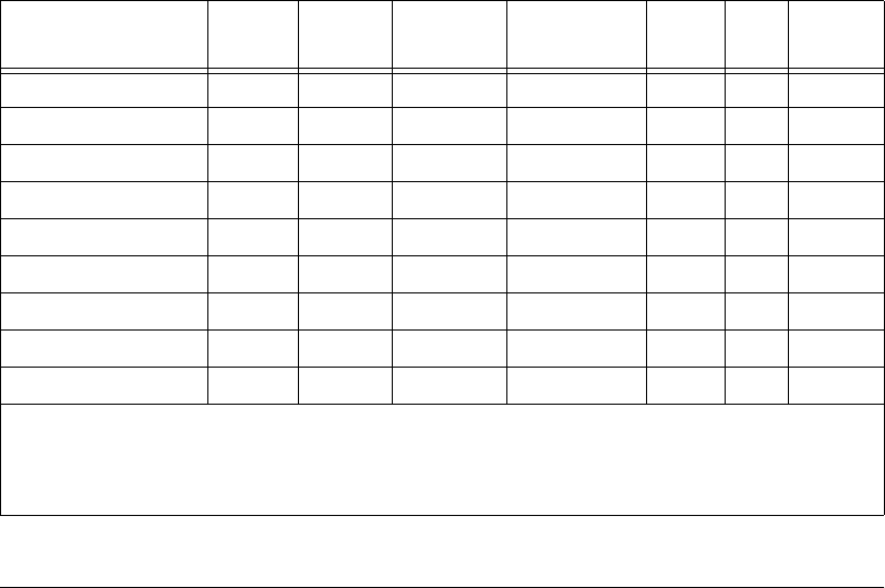
Table 4-3. I/O Signal Summary (Continued)
SignalName
Signal
Type and
Direction
Impedance
Input/
Output
Protection
(Volts)
On/Off
Source
(mA at V)
Sink
(mA
at V)
Rise
Time
(ns)
Bias