


Chapter 4 Signal Connections
© National Instruments Corporation 4-43 6023E/6024E/6025E User Manual
signal. You must configure the PFI pin you select as the source for the
UISOURCE signal in the level-detection mode. You can configure the
polarity selection for the PFI pin for either active high or active low.
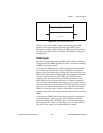
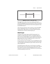
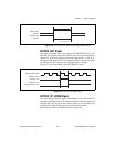
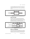
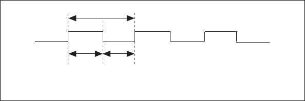
Figure 4-34 shows the timing requirements for the UISOURCE signal.
Figure 4-34.
UISOURCE Signal Timing
The maximum allowed frequency is 20 MHz, with a minimum pulse width
of 23 ns high or low. There is no minimum frequency limitation.
Either the 20 MHz or 100 kHz internal timebase normally generates the
UISOURCE signal unless you select some external source.
General-Purpose Timing Signal Connections
The general-purpose timing signals are GPCTR0_SOURCE,
GPCTR0_GATE, GPCTR0_OUT, GPCTR0_UP_DOWN,
GPCTR1_SOURCE, GPCTR1_GATE, GPCTR1_OUT,
GPCTR1_UP_DOWN, and FREQ_OUT.
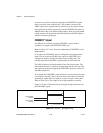
GPCTR0_SOURCE Signal
Any PFI pin can externally input the GPCTR0_SOURCE signal, which is
available as an output on the PFI8/GPCTR0_SOURCE pin.
As an input, the GPCTR0_SOURCE signal is configured in the
edge-detection mode. You can select any PFI pin as the source for
GPCTR0_SOURCE and configure the polarity selection for either rising
or falling edge.
As an output, the GPCTR0_SOURCE signal reflects the actual clock
connected to general-purpose counter 0. This is true even if another PFI
is externally inputting the source clock. This output is set to high
impedance at startup.
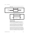
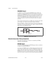
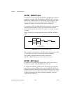
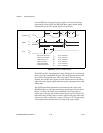
t
p
t
w
t
w
t
p
t
w
= 50 ns minimum
= 23 ns minimum