


46
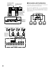
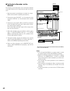
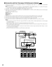
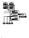
■ Connection with the Time-lapse VCR (Panasonic Models)
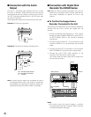
1. Configure the parameters of the Multiplexer functions in the Multiplexer Mode (refer to p. 98) window of WJ-SX150A
Administrator Console.
Note: To put a file from PC to the unit, select PC in 600 RECORDER in SETUP MENU. (Refer to p. 71.) When VCR is select-
ed, parameter configuration in the Multiplexer Mode window is unavailable.
2. After Step 1, select VCR for 600 RECORDER in SETUP MENU. (Refer to p. 71.)
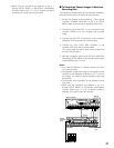
3. Conform the communication speed (SPEED) for 740 CAMERA/DATA 1- 4 PORT in SETUP MENU to that of the time-lapse
VCR. (Refer to pp. 74 and 75.)
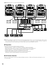
The following parameters are fixed.
Data bit: 7 bits
Parity check: ODD
Stop bit: 1 bit
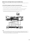
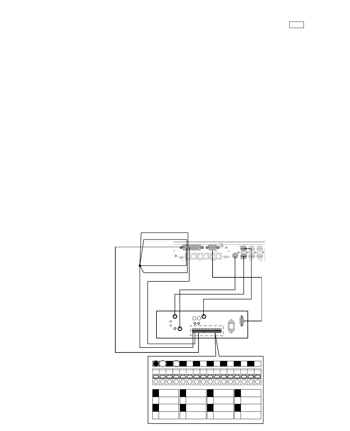
4. Connect the matrix switcher’s EXT OUT (REC OUT) to the time-lapse VCR’s VIDEO IN with the coaxial cable.
5. Connect the matrix switcher’s EXT IN (PLAY IN) to the time-lapse VCR’s VIDEO OUT with the coaxial cable.
6. Connect the matrix switcher’s SERIAL to that of the time-lapse VCR with a 9-pin D-sub cable.
7. Connect the matrix switcher’s CAMERA SW IN to the time-lapse VCR’s CAMERA SW OUT with an RCA-pin cable.
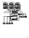
Notes:
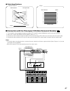
• Only Panasonic time-lapse VCRs which support RS-232C are usable. (Refer to Cable Specifications on the next page
for details of cables.)
• Both of the time-lapse VCR and PC cannot be connected to the matrix switcher.
• When configuring the system through WJ-SX150A Administrator Console, pull out the time-lapse VCR’s cable and con-
nect the PC’s cable to the serial port.
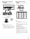
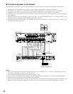
• To use the alarm recording function, connect the matrix switcher’s all alarm output terminals (Alarm Output 1 to 4) to
the time-lapse VCR’s ALARM IN.
• Be sure to activate auto-recovery for the VCR’s alarm reset function.
MUX
VIDEO IN
CAMERA
SW OUT
GND
S-VIDEO
AUDIO
VIDEO OUT
1
2
1 2 3 4 5 6 7 8 9 10 11 12 13 14 15 16
1
2
3
4
ALARM
IN
COM
ALARM
RESET IN
ALARM
RECOVER OUT
5
6
7
8
ALARM
OUT
1 SHOT IN
TAPE END
OUT
9
10
11
12
WARNING
OUT
HUMID OUT
REC REVIEW
OUT
13
14
15
16
SERIES
REC IN
TIME
ADJUST IN
TIME
ADJUST OUT
COM REC OUT
SERIES
REC OUT
Time-lapse VCR
Matrix Switcher
2
DATA 3 DATA 2
SERIALALARM
TERM
OFF ON
4
2
1
4
3
CAMERA
SW IN
RS485(CAMERA)
LINE
SELECT
MONITOR OUT
EXT IN
(PLAY IN)
EXT OUT
(
REC OUT
)
RS485(CAMERA)
DATA 4DATA HDR
PS•DATA
DATA 1
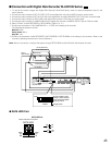
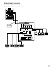
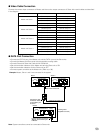
Pin #23(Alarm out 2)
Pin #9(GND)
Pin #24(Alarm out 4)
Pin #10(Alarm out 1)
Pin #11(Alarm out 3)
Pin #13
(Recover Input)
4