


54
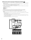
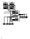
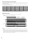
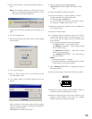
Connect the cameras and the Master/Slave 1 to 4 with the coaxial cables according to the diagram.
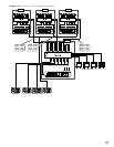
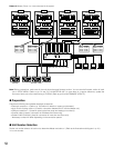
● Recorder Connection
Connect recorders to each Master/Slave units. Refer to pp. 40 to 47 for connection procedures.
Example: Master, Slave 1 and 2 are connected in the system.
Notes:
• Recorders and/or the Multiplexer board cannot be connected to the Master unit when Slave 1 to 4 are connected in the
system.
• The Master unit’s camera channels which loop thru Slave units cannot be connected to the recorder. (In the illustration, the
Master unit’s CAM OUT 1 to 8 and the recorder’s VIDEO IN 1 to 8 cannot be connected.) The Master recorder can record
only images from directly-connected cameras when the Master and Slave 1/2/3 are connected together. (For example in
the illustration, the Master recorder can record images from Cam 33 to 40.) Camera input signals from Slave units to the
Master unit are not for recording but for cross point switching.
CAMERA
1
1
2
2
3
3
OUT
IN
4
4
5
5
6
6
7
7
8
8
9
9
10
10
11
11
12
12
13
13
14
14
15
15
16
16
40 39 38 37 36 35 34 33
Connected to Slave 2 Connected to Slave 1
Master unit
Master recorder
Camera
16
16
15
15
14
14
13
13
12
12
11
11
10
10
9
9
8
8
7
7
6
6
5
5
4
4
3 2
23
1
1
VIDEO
IN
OUT
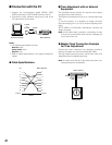
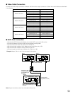
● Connection between the Units and Cameras
Connect each camera to CAMERA IN 1 to 16 of each unit. (Refer to p. 36 Connection with the Camera Sites.) Each camera has
its own logical camera number.
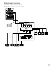
The default setting of the logical camera numbers is as follows. (The logical camera numbers can be configured in SETUP
MENU and WJ-SX150A Administrator Console.)
Camera total
number
1 to 16
17 to 28
29 to 40
41 to 52
53 to 64
1 to 16
17 to 28
33 to 40
49 to 52
–
–
1 to 16
1 to 16
1 to 16
1 to 16
–
–
17 to 32
17 to 32
17 to 32
–
–
–
33 to 48
33 to 48
–
–
–
–
49 to 64
Cameras connected
to Master
Cameras connected
to Slave 1
Cameras connected
to Slave 2
Cameras connected
to Slave 3
Cameras connected
to Slave 4