72
Without the Multiplexer board
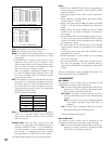
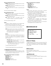
HD500: Select this when a WJ-HD500 Series recorder
is connected to the unit.
HD200: Select this when a WJ-HD200 Series recorder
is connected to the unit.
OFF: Select this when no recorder is connected to the
unit.
The factory default setting is HD500.
With the Multiplexer board
VCR: Select this when a time-lapse VCR (Panasonic
model) is connected to the unit.
HD100: Select this when a WJ-HD100 Series recorder
is connected to the unit.
OFF: Select this when a time-lapse VCR (non-
Panasonic model) or no recorder is connected.
The factory default setting is OFF.
Notes:
• If HD500 or HD200 is selected for the unit with the Mul-
tiplexer board, the parameter will be set to OFF.
• If VCR or HD100 is selected for the unit without the Mul-
tiplexer board, the parameter will be set to HD500.
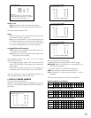
ADR: This stands for the recorder’s unit address. When
a digital disk recorder is connected to the unit, 1 to
99 is available. When a time-lapse VCR is connect-
ed, this parameter is not displayed.
EXT IN:
This stands for the setting of the EXT IN connector at
the unit’s rear panel. When the Multiplexer board is
installed in the Master unit, this parameter for MASTER
does not appear.
GENLOCK ON: Select this mode if you gen-lock
the unit with an external device.
GENLOCK OFF: Select this mode if you connect
the video output connector of the recorder to
the EXT IN connector of the unit.
The factory default setting is OFF.
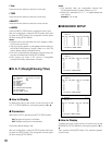
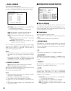
The factory default setting is same as the illustration.
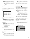
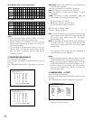
• COMMUNICATION STATUS
The following are communication parameters of a digi-
tal disk recorder/time-lapse VCR. The parameters will
differ depending on connected devices.
When a digital disk recorder is connected
DATA BIT: 8 bit
PARITY BIT: NONE
STOP BIT: 1 bit
BAUD RATE: 9600 bps
COMM PORT: DATA HDR PORT
When a time-lapse VCR is connected
DATA BIT: 7 bit
PARITY BIT: ODD
STOP BIT: 1 bit
BAUD RATE: 9600 bps
COMM PORT: SERIAL PORT
Notes:
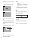
• 620 SLAVE1, 630 SLAVE 2, 640 SLAVE 3, and 650
SLAVE 4 appear only when they are connected.
• When Slave 1 to 4 are connected in the system, “---“ is
displayed for CONTROL of 610 MASTER.
• If GENLOCK ON is selected, the playback images or
multiscreen display cannot be displayed on Monitor 1
to 4. Confirm the images on the monitor which are con-
nected to the recorder.
• If GENLOCK OFF is selected, the maximum rate
recording becomes unavailable (when a WJ-HD500
Series recorder is connected to the unit).
• Gen-lock is not activated for the Slave 1 to 4 units when
the Multiplexer board is installed in them.
■ SYSTEM SETUP
● How to Display
To display this menu on the monitor, move the cursor to 700
SYSTEM in SETUP MENU by moving the joystick to ▼ or ▲.
Then, press the CAM (SET) button. The submenu appears
on the monitor.
● Parameters
Move the joystick to move the cursor.
Press the NEXT or PREV button to select the desired para-
meters.
• MASTER-SLAVE
This menu links to the submenu.
Move the cursor and press the CAM (SET) button to go into
the menu.
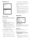
710 MASTER-SLAVE will appear on the monitor.
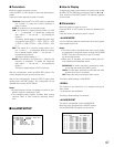
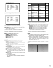
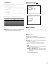
700 SYSTEM
710 MASTER-SLAVE
O
720 LOGICAL CAMERA NUMBERO
730 COMPENSATION/VD2/DATAO
740 CAMERA/DATA1-4 PORTO
750 RS485 CAMERAO
760 CAMERA CLEANING OFF


