


3810Plus and 3820Plus Installation
2-53980-A2-GB30-20 November 1996
3820
Plus
2-Wire Leased-Line
Network Connection
Obtain
a JM8 to RJ1
1 (8-position to 6-position)
crossover modular cable. See the equipment list in
Appendix H for part number information, and Appendix E
for a wiring diagram.
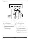
Use the following procedure to connect a
3820Plus modem to the leased-line network interface:
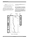
1. Insert the 6-position, 6-conductor modular plug
into the jack labeled DIAL/LEASED (3820Plus)
(Figure 2-3).
2. Insert the other end of the modular cord into the
leased-line network interface (“demarc”).
AC Power Supply Connection
WARNING
Power supplies from other
modems may fit into the
POWER connector, but
connecting the wrong power
supply can cause damage to
the modem or the power
supply.
Use the following procedure to connect the modem to
an ac power outlet:
1.
Make sure the modem’
s power switch is in the Of
f
position.
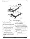
2. Insert the power transformer’s cylindrical
connector into the modem’s rear panel power
receptacle (Figure 2-2 or Figure 2-3).
3. Connect the power supply to a grounded ac power
outlet.
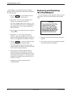
Network Management
System Connection
For the 3810Plus or 3820Plus
modem, use the
following procedure to connect the modem to the network
management system interface:
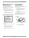
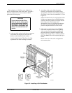
1. Insert the subminiature 4-position, 4-conductor
modular plug of the 3600 Hubbing Device
(Figure 2-4) into the jack labeled NMS
(Figure 2-2 or 2-3).
2. Connect the 3600 Hubbing Device to the network
management system.
Refer to the
3600 Hubbing Device, Featur
e Number
3600-F3-300, Installation Instructions for more
information. Installation for the 3810Plus or 3820Plus
modem is the same as for the 3610 DSU.
3000HUBBING DEVICE
MODEL #3000-F3-300
8-Pin
Modular
Jacks
6 Inches
Overall
4-Pin
Modular
Plug
496-13775-03
8
1
Pin
Numbers
8
1
CC IN/DC OUT
CC OUT/DC IN
CC IN/DC OUT
Hubbing Device
CC OUT/DC IN
Figure 2-4. 3600 Hubbing Device