


Model 3810 and 3820 Installation
2-33810-A2-GB30-20 November 1996
Customer-Supplied Equipment
The following customer
-supplied equipment is
required to complete a data communications system using
either the Model 3810 or Model 3820 modem:
• A DTE with an available EIA-232-D serial port.
• A standard EIA-232-D male-to-female cable with a
male DB-25-S connector at one end to attach to the
modem.
• One of the following modular dial or leased
network interfaces:
— RJ45S for dial programmable applications
— RJ1
1C for dial permissive applications
— An 8-position to 6-position crossover cable for
JM8 leased-line applications only
The following customer
-supplied equipment is
required for the installation of a Model 3811 modem:
• A COMSPHERE 3000 Series Carrier.
• A male-to-female 50-pin mass termination cable.
One Network Interface Module (NIM) for modems
installed in Slots 1–8 and one NIM for modems
installed in Slots 9–16 (required for dial-line
applications).
• One of the following modular or 50-pin dial or
leased network interfaces:
— RJ11C for single line dial permissive
applications
— RJ45S for single line dial programmable
applications
— RJ21X for multiple line dial permissive
applications
— RJ27X for multiple line programmable
applications
— 66 punchdown block or other demarcation
device
• One 6-position to 6-position modular cord (required
for network management applications).
• A Shared Diagnostic Unit (SDU) (required for
network management applications).
If the modem is to be managed by a network
management system, a Shared Diagnostic Unit (SDU)
must be supplied and properly connected to the network
management controller. For proper network management
connection to the SDU, refer to the COMSPHERE
6700 Series Network Management System User
’
s Guide
.
For installation of the 3000 Series Carrier into a
cabinet, refer to the
COMSPHERE 3000 Series Carrier
,
Installation Manual.
Model 3810 or Model 3820
Modem Installation
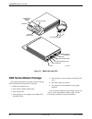
Before
installing your standalone modem, make sure
your installation site is clean and well-ventilated. Allow
space around the modem for installing cables and
telephone cords, and make sure the modem is located
within reach of the ac power outlet. The distance between
your modem and DTE should be minimized if DTE data
rates exceed 19,200 bps. Also, low capacitance cables
may be necessary for speeds greater than 19,200 bps or
distances greater than 50 feet.
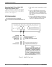
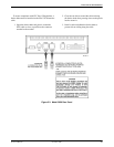
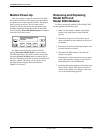
The rear panel of both the Model 3810 and Model 3820
modems have the following switches and connectors (see
Figures 2-2 and 2-3 which appear later in this chapter):
• An ON/Off power switch.
• A 5-pin DIN type power receptacle for ac power
transformer.
• An 8-pin modular keyed jack for 4-wire/2-wire
leased lines or external telephone set on the
Model 3810. On the Model 3820, this jack is for
external telephone set use only
.
• An 8-pin modular keyed jack for dial (Public
Switched Telephone Network, or PSTN) lines on
the Model 3810. On the Model 3820, this jack is for
dial or 2-wire leased lines.
• A 4-pin modular jack for Network Management
System (NMS) connection for future release.
• A 25-pin DB-25-S receptacle for DTE interface.