


4-13810-A2-GB30-20 November 1996
DCP Operation
Overview 4-1. . . . . . . . . . . . . . . . . . . . . . . . . . . . . . . . . . . . . . . . . . . . . . . . . . . . . . . . . . . . . . . . . . . . . . . . .
Diagnostic Control Panels 4-1. . . . . . . . . . . . . . . . . . . . . . . . . . . . . . . . . . . . . . . . . . . . . . . . . . . . . . . . . . . .
Models 3810 and 3820 Diagnostic Control Panels 4-1. . . . . . . . . . . . . . . . . . . . . . . . . . . . . . . . . . . . . . .
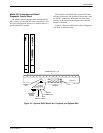
Model 3811 Faceplate and Shared Diagnostic Control Panel 4-3. . . . . . . . . . . . . . . . . . . . . . . . . . . . . . .
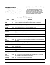
Status Indicators 4-4. . . . . . . . . . . . . . . . . . . . . . . . . . . . . . . . . . . . . . . . . . . . . . . . . . . . . . . . . . . . . . . . . . . .
Diagnostic Control Panel Operation 4-6. . . . . . . . . . . . . . . . . . . . . . . . . . . . . . . . . . . . . . . . . . . . . . . . . . . .
LCD Display 4-6. . . . . . . . . . . . . . . . . . . . . . . . . . . . . . . . . . . . . . . . . . . . . . . . . . . . . . . . . . . . . . . . . . . .
Hidden Choice Indicators 4-6. . . . . . . . . . . . . . . . . . . . . . . . . . . . . . . . . . . . . . . . . . . . . . . . . . . . . . .
Keypad 4-6. . . . . . . . . . . . . . . . . . . . . . . . . . . . . . . . . . . . . . . . . . . . . . . . . . . . . . . . . . . . . . . . . . . . . . . .
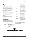
Menu Structure 4-7. . . . . . . . . . . . . . . . . . . . . . . . . . . . . . . . . . . . . . . . . . . . . . . . . . . . . . . . . . . . . . . . . . . .
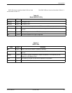
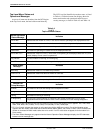
Top-Level Menu Status and Operational Messages 4-8. . . . . . . . . . . . . . . . . . . . . . . . . . . . . . . . . . . . . .
Selecting Factory Configuration Options 4-13. . . . . . . . . . . . . . . . . . . . . . . . . . . . . . . . . . . . . . . . . . . . . . . . .
Using the Diagnostic Control Panel 4-13. . . . . . . . . . . . . . . . . . . . . . . . . . . . . . . . . . . . . . . . . . . . . . . . . .
Using AT Commands 4-13. . . . . . . . . . . . . . . . . . . . . . . . . . . . . . . . . . . . . . . . . . . . . . . . . . . . . . . . . . . . . .
Overview
This
chapter describes how to use the diagnostic
control panel (DCP) of the 3800 Series modem. It also
describes how to select and use each branch of the
Top-Level menu tree.
Diagnostic Control Panels
There are two types of DCPs: the front panel on the
standalone Model 3810 and Model 3820 modems, and the
shared diagnostic control panel (SDCP), an optional
feature used with a Model 381
1 installed in a
COMSPHERE 3000 Series Carrier
. Both DCPs have a
two-line, 32-character liquid crystal display (LCD) and
keypad through which Top-Level menu branches are
accessed to perform the following:
• Initiate and disconnect dial operations
•
Check modem status
• Set up configuration options
•
Initiate diagnostic tests
• Access remote modems through the local modem’s
DCP
The LCD displays the result of any command initiated
using the DCP
. Most of these operations can be performed
from an attached asynchronous DTE using the
AT command set.
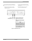
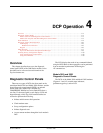
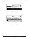
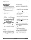
Models 3810 and 3820
Diagnostic Control Panels
The
DCPs of the Model 3810 and Model 3820 modems
(Figures 4-1 and 4-2) contain status indicators,
pushbutton-type keys, and an LCD.
4