


Model 3810 and 3820 Installation
2-73810-A2-GB30-20 November 1996
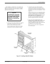
Model 3810 4-Wire/2-Wire
Leased-Line Connection
Use the following procedures to connect a Model 3810
to the leased-line network interface:
1. Insert the 8-position, 8-conductor modular plug
into the jack labeled PHONE/LEASED (3810),
Figure 2-2.
2. Insert the other end of the modular cord into the
leased-line network interface.
3. If the Model 3810 has a dial backup line, follow
the steps listed in
Model 3810 Dial-Line
Connection
section.
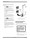
Model 3820 2-Wire
Leased-Line Connection
Use the following procedures to connect a Model 3820
modem to the 6-pin, center pair, leased-line network
interface. For 2-wire leased line connection to a JM8
network interface, refer to Figure E-1 in Appendix E:
1. Insert the 6-position, 4-conductor modular plug
into the jack labeled DIAL/LEASED (3820),
Figure 2-3.
2. Insert the other end of the modular cord into the
leased-line network interface.
Model 3810 and Model 3820
Telephone Connection
Use the following procedures to connect the modem to
a telephone:
1. Insert the 6-position, 4-conductor modular plug
into the jack labeled PHONE/LEASED (3810).
2. Insert the other end of the modular cord into the
telephone.
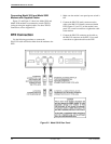
Dial Network Management
System Connection
For
Model 3810 and 3820 modems, use the following
procedures to connect the modem to the network
management system interface:
1. Insert the subminiature 4-conductor modular plug
of the 3600 Hubbing Device into the jack labeled
NMS (Figure 2-2 or 2-3).
2. Connect the 3600 Hubbing Device to the network
management system.
Refer to the
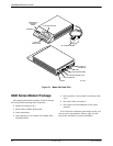
3600 Hubbing Device Featur
e Number
3600-F3-300 Installation Instructions (3610-A2-GZ45)
for more information. Installation for the Model 3810 and
3820 modems is the same as for the 3610 DSU.
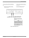
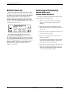
AC Power Transformer
Connection
Use the following procedures to connect the modem to
an ac power outlet:
1.
Make sure the modem’
s power switch is in the Of
f
position.
2. Insert the power transformer’s 5-pin DIN male
connector into the modem’s rear panel ac power
receptacle (Figures 2-2 and 2-3).
3. Insert the power transformer into a grounded ac
power outlet.