


S3C8275X/F8275X/C8278X/F8278X/C8274X/F8274X WATCH TIMER
12-1
12 WATCH TIMER
OVERVIEW
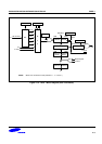
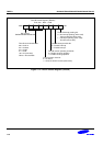
Watch timer functions include real-time and watch-time measurement and interval timing for the system clock. To
start watch timer operation, set bit 1 of the watch timer control register, WTCON.1 to "1".
And if you want to service watch timer overflow interrupt (IRQ 2, vector F6H), then set the WTCON.6 to "1".
The watch timer overflow interrupt pending condition (WTCON.0) must be cleared by software in the application's
interrupt service routine by means of writing a "0" to the WTCON.0 interrupt pending bit.
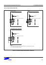
After the watch timer starts and elapses a time, the watch timer interrupt pending bit (WTCON.0) is automatically
set to "1", and interrupt requests commence in 3.91ms, 0.25, 0.5 and 1-second intervals by setting Watch timer
speed selection bits (WTCON.3− .2).
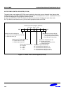
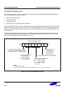
The watch timer can generate a steady 0.5 kHz, 1 kHz, 2 kHz, or 4 kHz signal to BUZ output pin for Buzzer. By
setting WTCON.3 and WTCON.2 to "11b", the watch timer will function in high-speed mode, generating an
interrupt every 3.91 ms. High-speed mode is useful for timing events for program debugging sequences.
A
lso, you can select watch timer clock source by setting the WTCON.7 appropriately value.
The watch timer supplies the clock frequency for the LCD controller (f
LCD
). Therefore, if the watch timer is
disabled, the LCD controller does not operate.
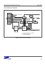
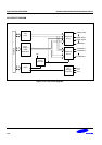
Watch timer has the following functional components:
• Real Time and Watch-Time Measurement
• Using a Main or Sub Clock Source (Main clock divided by 2
7
(fx/128) or Sub clock(fxt))
• Clock Source Generation for LCD Controller (f
LCD
)
• I/O pin for Buzzer Output Frequency Generator (P0.7, BUZ)
• Timing Tests in High-Speed Mode
• Watch timer overflow interrupt (IRQ 2, vector F6H) generation
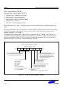
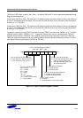
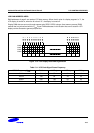
• Watch timer control register, WTCON (set 1, bank 1, E1H, read/write)