


SERIAL I/O INTERFACE S3C8275X/F8275X/C8278X/F8278X/C8274X/F8274X
14-2
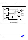
SIO CONTROL REGISTERS (SIOCON)
The control register for serial I/O interface module, SIOCON, is located at E1H in set 1, bank 0. It has the control
setting for SIO module.
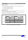
• Clock source selection (internal or external) for shift clock
• Interrupt enable
• Edge selection for shift operation
• Clear 3-bit counter and start shift operation
• Shift operation (transmit) enable
• Mode selection (transmit/receive or receive-only)
• Data direction selection (MSB first or LSB first)
A reset clears the SIOCON value to "00H". This configures the corresponding module with an internal clock
source at the SCK, selects receive-only operating mode, and clears the 3-bit counter. The data shift operation
and the interrupt are disabled. The selected data direction is MSB-first.
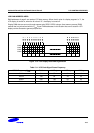
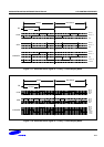
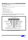
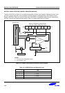
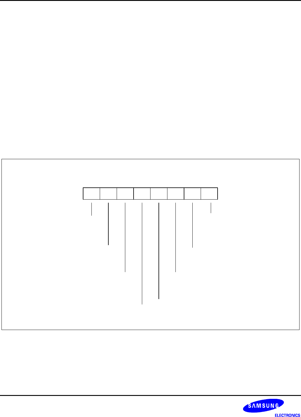
Serial I/O Module Control Register (SIOCON)
E1H, Set 1, Bank 0, R/W
.7 .6 .5 .4 .3 .2 .1 .0MSB LSB
SIO interrupt enable bit:
0 = Disable SIO interrupt
1 = Enable SIO interrupt
SIO interrupt pending bit:
0 = No interrupt pending
0 = Clear pending condition
(when write)
1 = Interrupt is pending
SIO shift operation enable bit:
0 = Disable shifter and clock counter
1 = Enable shifter and clock counter
Shift clock edge selection bit:
0 = T
X
at falling edges, Rx at rising edges
1 = T
X
at rising edges, Rx at falling edges
Data direction control bit:
0 = MSB-first mode
1 = LSB-first mode
SIO mode selection bit:
0 = Receive only mode
1 = Transmit/receive mode
SIO counter clear and shift start bit:
0 = No action
1 = Clear 3-bit counter and start shifting
SIO shift clock selection bit:
0 = Internal clock (P.S Clock)
1 = External clock (SCK)
Figure 14-1. Serial I/O Module Control Register (SIOCON)