


Flex-MuxOneNAND4G(KFM4GH6Q4M-DEBx)
- 86 -
FLASH MEMORY
Flex-MuxOneNAND8G(KFN8GH6Q4M-DEBx)
Flex-MuxOneNAND16G(KFKAGH6Q4M-DEBx)
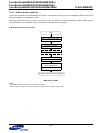
3.12.1 PI Block Boundary Information setting
It is 1st word of sector0 of page0 of main area of PI Block. The Lock bits for PI Block and Boundary address of SLC and MLC are stored. After
shipment, it is initially programmed as data FC00h(Lock bit[15:14]: 11b(binary), Boundary address[9:0]: 000h).
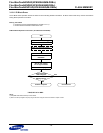
To change PI Block contents (i.e, lock bits and boundary address), Erase/Program sequence should be followed as below.
PI Block Boundary Information setting steps
Enter PI Block access mode(
Refer to Chapter 3.12.1.1)
.
Issue PI Block erase(
Refer to Chapter 3.12.1.2)
.
Issue PI program(
Refer to Chapter 3.12.1.3)
.
Exit PI Block Access mode & Update new Partition Information.
PI block Access mode exit can be done through a Warm/Cold/Hot/NAND Flash Reset.
However, PI Update can only be done by two methods: PI Update Command and Cold Reset.
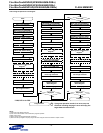
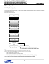
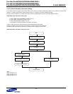
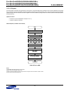
The following flow chart shows two methods for updating the PI and exiting PI access mode.
PI Block Boundary Information setting Flow Chart
NOTE :
1) Refer to Chapter 3.12.1.1
2) Refer to Chapter 3.12.1.2
3) Refer to Chapter 3.12.1.3
4) Refer to Chapter 3.12.1.4
PI Block Access mode entry
1)
PI Block Erase
2)
PI Program
3)
(Lock bit, Boundary of Address)
PI Block Update
4)
Cold Reset
Warm/Hot/NAND Flash Reset
PI Block Access Mode exit
PI Update done
Start