Page 5-9
Section 5. Mechanical Adjustments
SATO CL608e/CL612e Service Manual
PN 9001079
Rev. B
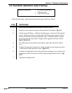
5.6 Feed Roller Adjustment (Label Tracking)
Required Equipment: #2 Pozidrv Screwdriver
5.5mm wrench
1 Kg Tension Gauge
STEP PROCEDURE
1. Switch the printer OFF and disconnect the power cable.
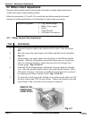
2. Raise the access door and remove the label stock if installed. Fig. 5-1
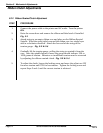
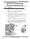
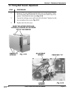
3. Attach a strip of 20mm + wide liner backing paper to the end of the tension
gauge. Under the media cover, place the strip between the pressure rollers
at one end with the print head assembly open. Gradually pull the tension
gauge and measure the friction. Repeat at the opposite end of the rollers.
Fig. 5-10 & 5-11
4. The difference between the left side and the right side should be 100g or
less.
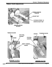
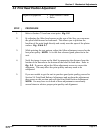
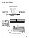
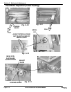
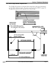
5. To adjust the pressure between the rollers, loosen the two fixing nuts with a
5.5mm wrench and adjust the screws. Fig. 5-12
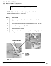
6. To adjust the alignment of the roller, loosen the locking screw and move the
adjust plate with a screwdriver until the required positions are found. Fig.
5-13
7. Tighten the locking screw.
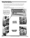
Used for fine tuning. Adjusts pressure between upper and lower rollers.


