


Page 5-11
Section 5. Mechanical Adjustments
SATO CL608e/CL612e Service Manual
PN 9001079
Rev. B
STEP PROCEDURE
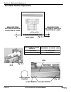
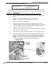
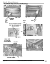
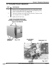
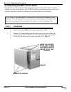
1. Remove (3) screws holding the left side cover to the printer. Raise
the access door and loosen the (2) screws on the inside top of the
printer. Lift off the left side cover. Fig. 5-14
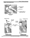
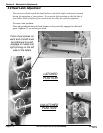
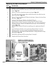
2. Loosen the locking screws and belts will self-adjust. Tighten, but do
not overtighten the screws. Fig. 5-15
3. Replace the left side cover.
ADJUSTMENT
SPRING
LOCKING
SCREWS
TIMING BELT "B"
Fig. 5-15
5.7 Timing Belt Tension Adjustment
Fig. 5-14
REMOVE (3)
SCREWS
RAISE THE ACCESS DOOR AND
LOOSEN (2) SCREWS ON THE INSIDE
TOP OF THE PRINTER