


Page 4-10
Section 4. Electric Checks and Adjustments
SATO CL608e/CL612e Service Manual
PN 9001079
Rev. B
4.6 Label Gap Adjustment
Additional equipment required: TP Test Module
Digital Multimeter
STEP PROCEDURE
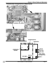
Refer to Section 4.2 for access to main PCB
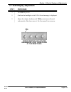
1. Turn VR4 (GAP) potentiometer on the main PCB all the way to the left.
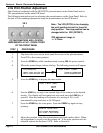
2. Refer to Section 4.3.
Set the digital multimeter to DC voltage measurement mode.
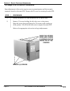
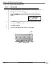
Attach the connector from the TP Test Module to the test port on the main
PCB. Note correct positioning of connector. Nibs on the connector are placed
down in the receptacle on the PCB in the forward position. Set the dial to 5.
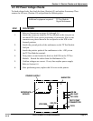
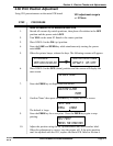
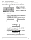
3. Connect (+) probe of the multimeter to Sig+ and (-) probe to pin GND.
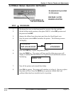
4. For Low level (Label Gap part with backing only) adjustment, put label gap
part in the sensor. Then adjust the electrical level with VR4 on the main
PCB so that it will measure less than 0.5 V.
5. For High level (paper part) adjustment, put paper part in the sensor and
check the electrical level. If the level difference is +1.0 V more than the Low
level, it is acceptable. If it is lower than 1.0V repeat STEPS 4 & 5 and
readjust VR4.
6 Standard values: Low level (gap): below 0.5 V
High level (paper part): Low level +1.0 V or
higher. If these values do not result, try the
following:
a) Repeat the process
b) Clean the sensor
c) Verify sensor is operational
d) Replace labels with higher quality labels
e) Perform factory reset