


Page 9-10
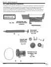
Section 9. Optional Accessories
SATO CL608e/CL612e Service Manual
PN 9001079
Rev. B
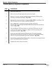
STEP PROCEDURE
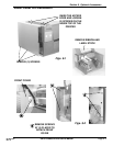
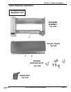
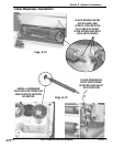
15. Refer to Fig. 9-8a and Figs. 9-18
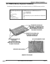
Install dispenser unit in its entirety to the front of the print cover previously
removed in Step 6 with (5) screws.
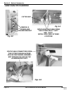
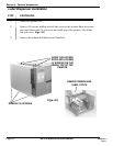
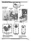
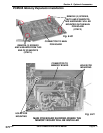
16. Refer to Fig. 9-8h and Figs. 9-19
Install cable stay in the approximate position shown in Figs. 9-19. Route
the dispenser cable under the stay and through opening in the printer to the
main PCB connector harness @ SEN3.
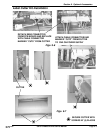
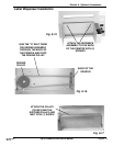
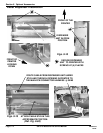
17. Disengage dispenser front door by grasping cut out section and lifting up and
forward.
18. Place DSW3-1 and DSW3-2 in the on position.
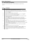
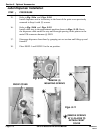
Label Dispenser Installation
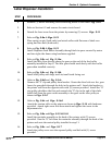
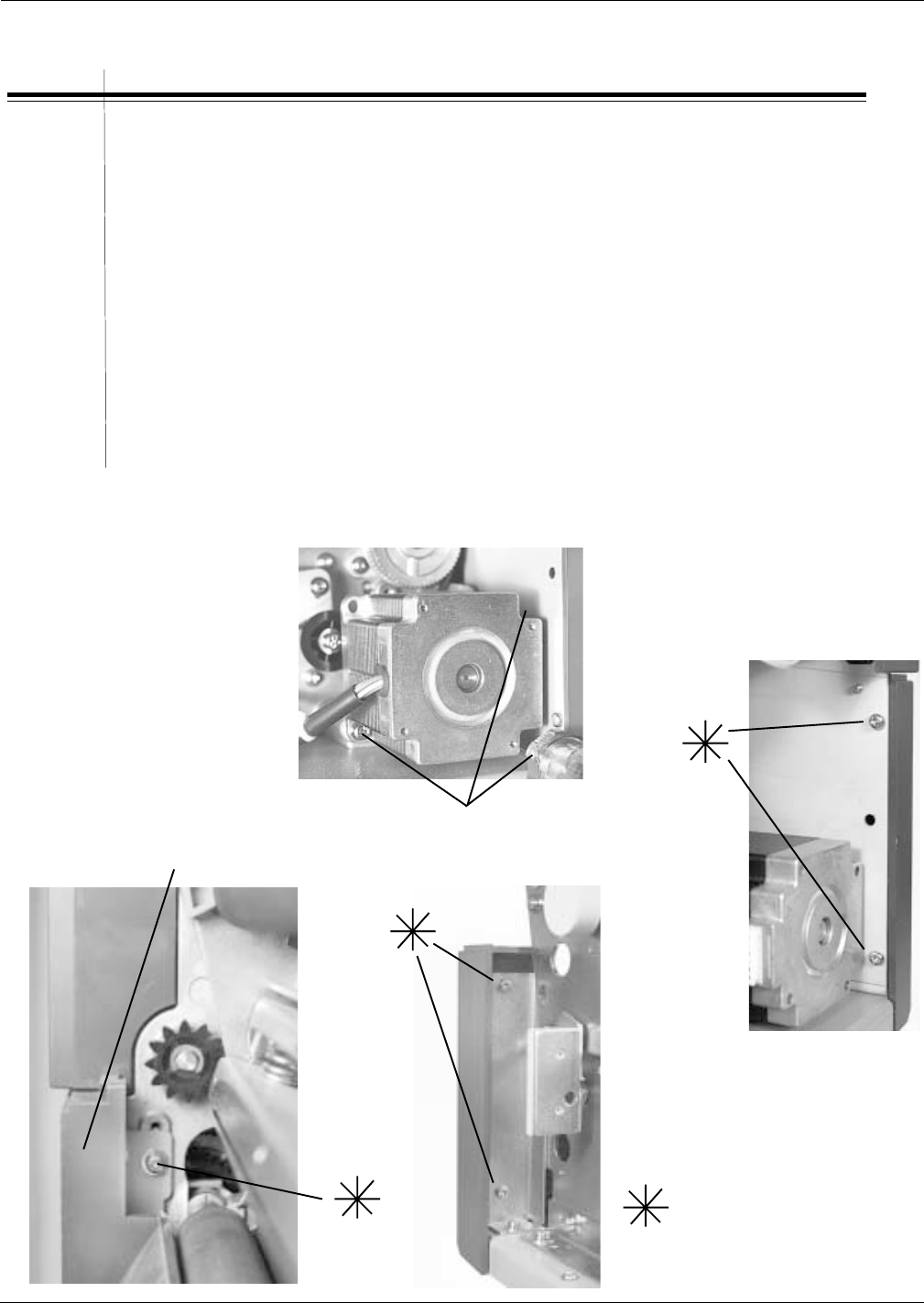
REMOVE (3)
MOUNTING SCREWS
Fig. 9-10
FRONT COVER
REMOVE SCREWS
AT (5) PLACES TO
DETACH FRONT
COVER
Figs. 9-11