


Page 4-2
Section 4. Electric Checks and Adjustments
SATO CL608e/CL612e Service Manual
PN 9001079
Rev. B
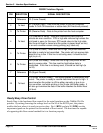
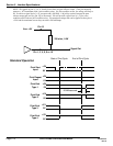
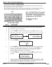
STEP PROCEDURE
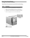
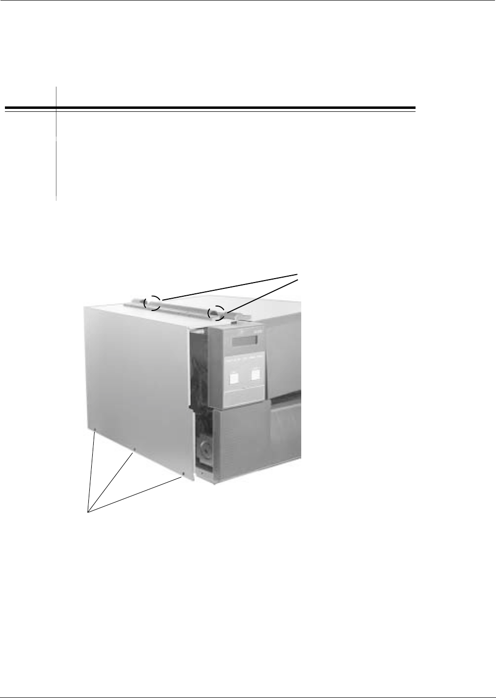
1. Switch the printer OFF and disconnect the AC power cord.
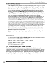
2. Remove (3) screws holding the left side cover to the printer.
Raise the access door and loosen the (2) screws on the inside top
of the printer. Lift off the left side cover to expose the main PCB.
Refer to the appropriate sub-section to begin adjustments.
REMOVE (3) SCREWS
RAISE THE ACCESS
DOOR AND LOOSEN
(2) SCREWS ON THE
INSIDE TOP OF THE
PRINTER
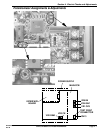
4.2 Steps Prior to Some Procedures
Some adjustments in this section require access to potentiometers and the test point
connector located on the main PCB. Remove the LH cover for accessing the main PCB.