


Functional Overview
ARM DDI 0389B Copyright © 2006 ARM Limited. All rights reserved. 2-13
an active output
<domain>_cactive
Where:
<domain> is ahb or smc.
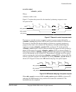
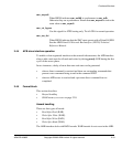
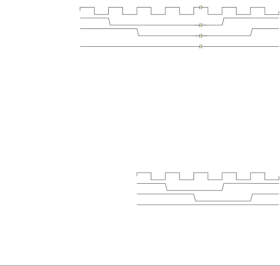
Figure 2-7 explains the protocol for the interface by showing a request to enter
low-power mode.
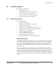
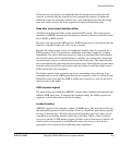
Figure 2-7 Request to enter low-power mode
The memory controller receives a request to enter low-power mode, indicated by
<domain>_csysreq being driven LOW by the system clock controller, as shown at T1.
The memory controller then has the chance to perform any required operations to
prepare for the clock to be switched off. The memory controller acknowledges the
request by asserting <domain>_csysack LOW, as shown at T2. At this point the
<domain>_cactive signal is used to indicate whether the request has been accepted or
denied. If the request is accepted, <domain>_cactive is LOW, as shown in Figure 2-7.
If the request is denied, <domain>_cactive is HIGH. If the request is accepted, then the
clock to that domain can be switched off. The peripheral is brought out of low-power
state by restarting the clock and driving <domain>_csysreq HIGH, as shown at T4. The
memory controller completes the handshake by driving <domain>_csysack HIGH, as
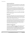
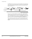
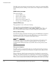
shown at T5. Figure 2-8 shows the AHB domain denying a low-power request.
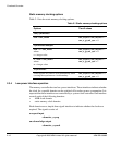
Figure 2-8 AHB domain denying a low-power request
When ahb_csysack is asserted LOW, the ahb_cactive signal is HIGH, as shown at T3,
indicating the AHB domain is busy and the clock cannot be switched off. The
handshake must be completed.
KFON
DKEBFV\VUHT
DKEBFV\VDFN
DKEBFDFWLYH
7 7 7 7 7
KFON
DKEBFV\VUHT
DKEBFV\VDFN
DKEBFDFWLYH
7 7 7 7