


126
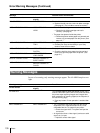
Others
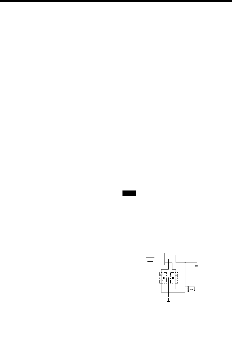
BUSY
MIN
GND
FL2 FL1
CN5
1
3
2
VIDEO (NTSC composite video
signal for NTSC/EIA standards
and PAL composite video
signal for PAL B.G.I standards)
BNC connector × 1
1 Vp-p, 75 ohms (terminated),
sync negative
Controls connectors
REMOTE 1 : special mini jack × 1
For RM-5500 Remote Control
Unit (not supplied)
REMOTE 2 (automatic printing
connector): Stereo mini jack :
× 1
For RM-91 Remote Control
Unit and FS-36 Foot Switch
REMOTE 3 (automatic printing
connector): D-SUB 9-pin
connector: × 1 For FS-30 Foot
Switch (not supplied)
(See “Selecting the Operation
Mode for Automatic Printing
Capabilities” page 104)
RS-232C (Computer control
interface): D-SUB 25-pin
connector × 1
Output: 5 kilohms at load
Typical ± 8 V
Input: 5-kilohm load
High level 5 to 15 V
Low level –5 to –15 V
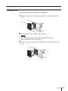
Supplied accessories
Color printing pack (1)
Ink ribbon holder (1)
Paper tray (1)
Paper cover (1)
Fan cover with a filter (1)
Thermal head cleaning kit (1)
AC power cord (1)
Warranty card (1)
(for UP-50/51MD/51MDU)
Instructions for Use (1)
Optional accessories
UPC-510 Color Printing Pack
UPC-540 Self-laminating Color
Printing Pack
Medical Specifications (for UP-51MD/51MDU/
51MDP)
Protection against electric shock:
Class I
Protection against harmful ingress
of water:
Ordinary
Degree of safety in the presence of
flammable anesthetics or
oxygen:
Not suitable for use in the
presence of flammable
anesthetics or oxygen
Mode of operation:
Continuous
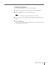
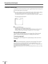
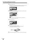
Using the automatic printing capabilities
(REMOTE 2/REMOTE 3)
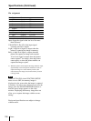
If you send remote control pulse signals illustrated
through the REMOTE 2 or REMOTE 3 connector,
the printer is remotely controlled according to the
remote control setting. (See page 104.)
Turn on the power of the printer and display the
source image on the monitor screen. Send a remote
control pulse signal at the timing shown below.
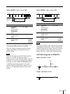
The timing depends on the setting on item
IMMED. CAP of the FUNCTION SETUP menu.
Note
The remote control pulse signal examples
introduced here are one example of typical
operation timing. The timing may be affected due
to the memory page selected and print type.
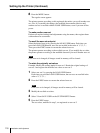
CAPTURE timing pulse for REMOTE 2
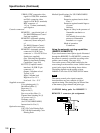
REMOTE 2 connector pin assignment:
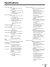
Specifications (Continued)