4-19
W
R S T
M N O
J
G H I
B C A D E F
Y Z
P
U
Q
V X
K L
AUTO
RESERVE
AUTO
GAIN
AUTO
PHASE
AUTO
SCALE
ALT EXP ENTER
0
_
CURSOR
MAX/MIN
.
1 3
CURSOR
SETUP
2
4 6
EDIT
MARK
5
7 9
MARK
8
START
CONT
CURSOR ACTIVE
DISPLAY
PAUSE
RESET
DISK
AUX
OUTPUTS
TRACE
SCAN
GAIN
TC
REF
PHASE
PRINT
SYSTEM
SETUP
MATH
DISPLAY
SCALE
OUTPUT
OFFSET
INPUT
FILTERS
HELP
MODEL SR850 DSP LOCK-IN AMPLIFIER
STANFORD RESEARCH SYSTEMS
SRS
AUTO
SYSTEM
MENU
ENTRY
CONTROL
100M /15pF
1M
REFERENCE IN
SIGNAL IN
SINE OUT
50
OUTPUT
<20mA
CH1 A-ICH2 B
Ω Ω
Ω
LOCAL
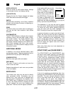
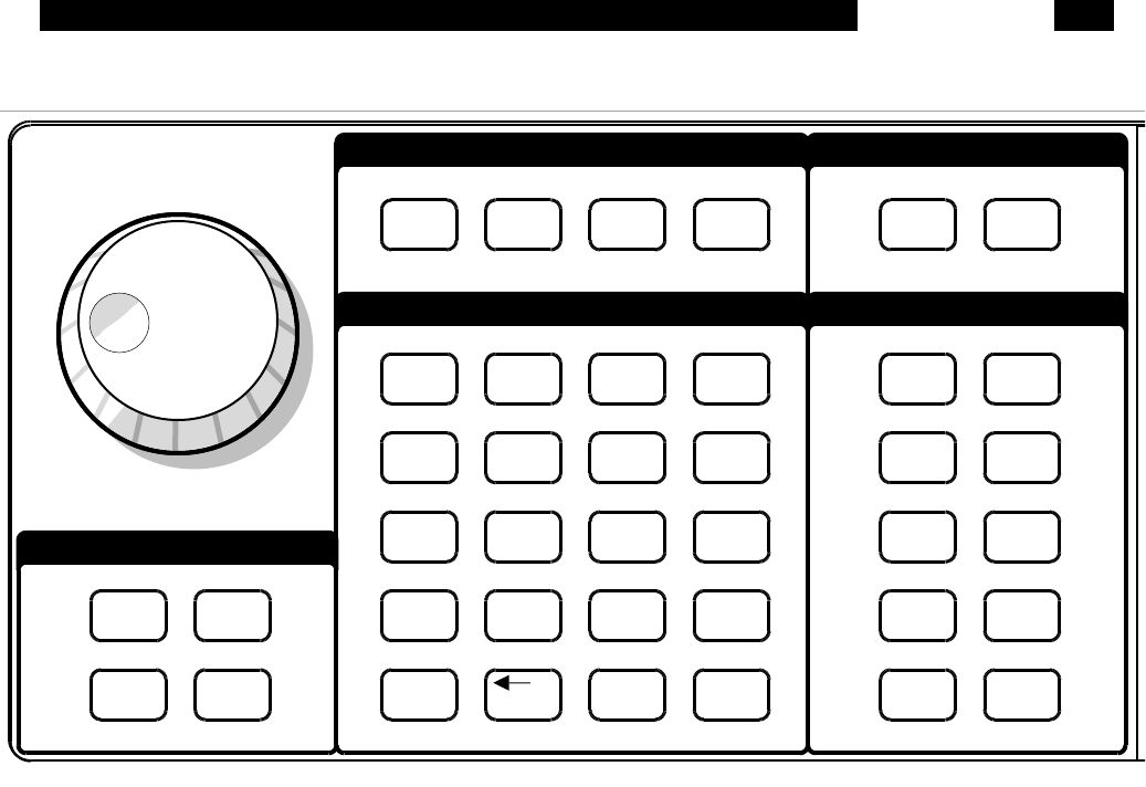
NORMAL AND ALTERNATE KEYS
The normal key definitions are printed on each
key. In addition, each key also has an alternate
definition printed below it. The [ALT] key toggles
the keypad between the two definitions. The ALT
screen indicator is on when the alternate defini-
tions are in use. The [0]...[9], [.], [-], [←] and [ALT]
keys have the same definition in both modes. The
alternate keys should only be used when access-
ing files on the disk drive or entering labels.
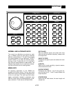
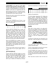
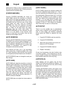
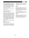
MENU KEYS
All operating parameters of the SR850 are
grouped into function menus. The ten menu keys
select which menu of parameters is displayed next
to the six soft keys. The soft keys then either
toggle a parameter, highlight a parameter entry
field (for numeric entry or knob adjustment), or dis-
play a submenu. These menus are listed below.
[REF/PHASE]
Sets the reference source and phase shift. Also
sets the internal oscillator frequency, sweep limits
and output level.
[INPUT/FILTERS]
Configures the signal inputs and selects the notch
prefilters.
[GAIN/TC]
Select the full scale sensitivity, dynamic reserve,
time constant and roll-off.
[OUTPUT/OFFSET]
Configures the Channel 1 and 2 front panel out-
puts and sets the X, Y and R output offsets and
output expands.
[TRACE/SCAN]
Define the four data traces, the scan length and
sample rate.
KEYPAD


