4-14
Screen Display
the scan length is only meaningful is parameters
are being swept. Once the trace buffer has looped
around, the oldest point (at any time) is at bin#0
and the most recent point is at bin#k where k is
the buffer length (minus 1).
The default mode is Loop.
Default Scan
Upon reset, all four traces are stored for a maxi-
mum of 16000 points. The sample rate is 1 Hz, the
scan length is 16000 seconds and the scan mode
is Loop. The trace definitions are X, Y, R and θ for
Traces 1-4.
Starting and Stopping a Scan
The [START/CONT] and [PAUSE/RESET] keys
are used to control data acquisition. Basically, the
[START/CONT] key starts a scan or continues a
paused scan and the [PAUSE/RESET] key pauses
a scan or resets a finished scan. See the discus-
sion of keypad operation later in this section for
details. Scans can also be controlled via the com-
puter interfaces. See the programming section for
an explanation.
In addition, the rear panel Trigger input can be
used to start a scan. To select this mode, set the
Trigger Starts option in the AUX menu. In this
mode, a rising TTL trigger will act the same as the
[START/CONT] key. The sample rate can be
either internal or Triggered. In the first case, the
trigger starts the scan and data is sampled at the
programmed sample rate (up to 512 Hz). In the
latter case, the first trigger will start the scan and
data will be sampled at every subsequent trigger.
Aliasing Effects
In any sampled data stream, it is possible to
sample a high frequency signal such that it will
appear to be a much lower frequency. This is
called aliasing.
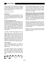
For example, suppose the lock-in is detecting a
signal near 1 Hz with a relatively short time con-
stant. The X output will have a DC component and
a 2 Hz component (2xf). If the sample rate is 2 Hz,
then the samples may be taken as illustrated
below.
The samples represent a sine wave much slower
than 2 Hz that isn't actually present in the output!
The chart display of this trace will show a sine
wave at a very low frequency and will be rather
misleading. In this case, a much higher sampling
rate will solve the problem.
Aliasing occurs whenever the output signal
being sampled contains signals at frequencies
greater than 1/2 the sample rate. The effect is
most noticeable when trying to sample an output
frequency at an integer multiple of the sample rate
(as above). The above aliasing problem will be the
same for a 1 kHz output (500 times the sample
rate) as for the 2 Hz output.
Generally, the highest possible sample rate should
be used given the desired scan length and number
of stored traces. The lock-in time constant and
filter slope should be chosen to attenuate signals
at frequencies higher than 1/2 the sample rate as
much as possible.
Aliasing can occur with the polar and bar graph
displays as well. These displays sample the output
signal at a fixed rate.
1 second


