2-4
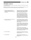
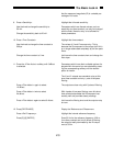
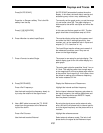
5. Press the <Rotate 90 deg> softkey.
Press the <deg.> softkey.
Use the knob to adjust the phase shift until Y
is zero and X is equal to the positive
amplitude.
Press [9] [0] [ENTER]
Press [AUTO PHASE]
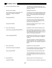
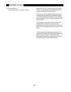
6. Press <Ref. Frequency>
Press [1] [2] [.] [3] [4] [5] [EXP] [3] [ENTER]
Press [1] [0] [0] [0] [ENTER]
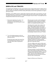
7. Press <Sine Output>
Use the knob to adjust the amplitude.
Press [.] [0] [1] [ENTER]
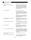
8. Press [GAIN/TC]
Press [AUTO GAIN]
This adds 90° to the reference phase shift. The
value of X drops to zero and Y becomes minus the
magnitude (-1.000 V).
Highlight the phase shift.
The knob can be used to adjust parameters which
are continuous, such as phase, amplitude and fre-
quency. The final phase value should be close to
zero again.
Phase shifts can also be entered numerically.
The knob is useful for small adjustments while
numeric entry is easier when changing to a pre-
cise value or by a large amount.
Use the Auto Phase function to return Y to zero
and X to the amplitude.
Highlight the internal reference frequency menu.
Enter 12.345 kHz in exponential form. The meas-
ured signal amplitude should stay within 1% of 1 V
and the phase shift should stay close to zero (the
value of Y should stay close to zero).
Parameters can be entered in real or integer form
as well. In this case, the frequency is changed to
1.000 kHz.
The internal oscillator is crystal synthesized with
25 ppm of frequency error. The frequency can be
set with 5 digit or 0.1 mHz resolution, whichever is
greater.
Highlight the sine output amplitude.
As the amplitude is changed, the measured value
of X should equal the sine output amplitude.
The amplitude may be entered numerically also.
The sine amplitude can be set from 4 mV to 5 V
rms into high impedance (half the amplitude into a
50 Ω load).
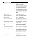
Display the Gain and Time Constant menu.
The Auto Gain function will adjust the sensitivity so
The Basic Lock-in


