4-2
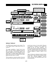
The main area of the display is occupied by the
output display(s). Both single and dual trace dis-
plays are available. In addition, each display can
be formatted as a large numeric readout with bar
graph, a polar graph, or a strip chart.
A complete description of the screen display
options follows in the next section.
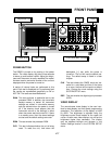
SOFT KEYS
The SR850 has a menu driven user interface. The
6 soft keys to the right of the video display have
different functions depending upon the information
displayed in the menu boxes at the right of the
screen. In general, the soft keys have two uses.
The first is to toggle a feature on and off or to
choose between various options. The second is to
highlight a parameter which is then changed using
the spin knob or numeric keypad. In both cases,
the soft keys select the parameters which are dis-
played adjacent to them.
KEYPAD
The keypad consists of five groups of keys. The
ENTRY keys are used to enter numeric parame-
ters which have been highlighted by a soft key.
The MENU keys select a menu of soft keys.
Pressing a menu key will change the menu boxes
which are displayed next to the soft keys. Each
menu presents a group of related parameters and
functions. The CONTROL keys start and stop
actual data acquisition, select the cursor and
toggle the active display. These keys are not in a
menu since they are used frequently and while dis-
playing any menu. The SYSTEM keys print the
screen to a printer and display help messages.
Once again, these keys can be accessed from any
menu. The AUTO keys perform auto functions and
are accessible from any menu.
A complete description of the keys follows in the
next section.
SPIN KNOB
The spin knob is used to adjust parameters which
have been highlighted using the soft keys. Most
numeric entry fields may be adjusted using the
knob. Some parameters with many options, sensi-
tivity for example, use the knob to select the
desired option. In addition, functions such as dis-
play zooming and scrolling use the knob as well.
In these cases, the knob function is selected by
the soft keys. The [CURSOR] key, which can be
pressed at any time, will set the knob function to
scrolling the cursor if there is a strip chart dis-
played.
DISK DRIVE
The 3.5" disk drive is used to store data and instru-
ment settings. Double sided, double density disks
should be used. The disk capacity is 720k bytes
formatted. The disk format is DOS compatible.
Disks written by the SR850 may be read by PC
compatible computers equipped with a 3.5" drive
and DOS 3.0 or higher.
Only use double sided double density (DS/DD)
disks. Do not use high density (DS/HD) disks.
FRONT PANEL BNC CONNECTORS
Refer to the previous section, SR850 Basics, for
detailed information about each input or output.
Reference Input
The reference input can be a sine wave (rising
zero crossing detected) or a TTL pulse or square
wave (rising or falling edge). The input impedance
is 1 MΩ AC coupled (>1 Hz) for the sine input. For
low frequencies (<1 Hz), it is necessary to use a
TTL reference signal. The TTL input provides the
best overall performance and should be used
whenever possible.
Sine Out
The internal oscillator output has a 50Ω output
impedance and varies in amplitude from 4 mVrms
to 5 Vrms. The output level is specified into a high
impedance load. If the output is terminated in a
low impedance, such as 50Ω, the amplitude will be
less than the programmed amplitude (half for a
50Ω load).
This output is active even when an external refer-
ence is used. In this case, the sine wave is phase
locked to the reference and its amplitude is pro-
grammable.
A TTL sync output is provided on the rear panel.
This output is useful for triggering scopes and
other equipment at the reference frequency. The
TTL sync output is a square wave derived from the
zero crossings of the sine output.
Front Panel


