


3-2
SR850 Basics
This is a very nice signal - it is a DC signal propor-
tional to the signal amplitude.
Narrow band detection
Now suppose the input is made up of signal plus
noise. The PSD and low pass filter only detect sig-
nals whose frequencies are very close to the lock-
in reference frequency. Noise signals at frequen-
cies far from the reference are attenuated at the
PSD output by the low pass filter (neither ω
noise
-
ω
ref
nor ω
noise
+ω
ref
are close to DC). Noise at fre-
quencies very close to the reference frequency will
result in very low frequency AC outputs from the
PSD (|ω
noise
-ω
ref
| is small). Their attenuation
depends upon the low pass filter bandwidth and
roll-off. A narrower bandwidth will remove noise
sources very close to the reference frequency, a
wider bandwidth allows these signals to pass. The
low pass filter bandwidth determines the band-
width of detection. Only the signal at the reference
frequency will result in a true DC output and be
unaffected by the low pass filter. This is the signal
we want to measure.
Where does the
lock-in reference come from?
We need to make the lock-in reference the same
as the signal frequency, i.e. ω
r
= ω
L
. Not only do
the frequencies have to be the same, the phase
between the signals can not change with time, oth-
erwise cos(θ
sig
- θ
ref
) will change and V
psd
will not
be a DC signal. In other words, the lock-in refer-
ence needs to be phase-locked to the signal
reference.
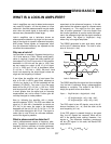
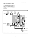
Lock-in amplifiers use a phase-locked-loop (PLL)
to generate the reference signal. An external refer-
ence signal (in this case, the reference square
wave) is provided to the lock-in. The PLL in the
lock-in locks the internal reference oscillator to this
external reference, resulting in a reference sine
wave at ω
r
with a fixed phase shift of θ
ref
. Since
the PLL actively tracks the external reference,
changes in the external reference frequency do
not affect the measurement.
All lock-in measurements
require a reference signal.
In this case, the reference is provided by the exci-
tation source (the function generator). This is
called an external reference source. In many situa-
tions, the SR850's internal oscillator may be used
instead. The internal oscillator is just like a func-
tion generator (with variable sine output and a TTL
sync) which is always phase-locked to the refer-
ence oscillator.
Magnitude and phase
Remember that the PSD output is proportional
to V
sig
cosθ where θ = (θ
sig
- θ
ref
). θ is the phase
difference between the signal and the lock-in refer-
ence oscillator. By adjusting θ
ref
we can make θ
equal to zero, in which case we can measure V
sig
(cosθ=1). Conversely, if θ is 90°, there will be no
output at all. A lock-in with a single PSD is called a
single-phase lock-in and its output is V
sig
cosθ.
This phase dependency can be eliminated by
adding a second PSD. If the second PSD multi-
plies the signal with the reference oscillator shifted
by 90°, i.e. V
L
sin(ω
L
t + θ
ref
+ 90°), its low pass fil-
tered output will be
V
psd2
= 1/2 V
sig
V
L
sin(θ
sig
- θ
ref
)
V
psd2
~ V
sig
sinθ
Now we have two outputs, one proportional to
cosθ and the other proportional to sinθ. If we call
the first output X and the second Y,
X = V
sig
cosθ Y = V
sig
sinθ
these two quantities represent the signal as a
vector relative to the lock-in reference oscillator. X
is called the 'in-phase' component and Y the
'quadrature' component. This is because when
θ=0, X measures the signal while Y is zero.
By computing the magnitude (R) of the signal
vector, the phase dependency is removed.
R = (X
2
+ Y
2
)
1/2
= V
sig
R measures the signal amplitude and does not
depend upon the phase between the signal and
lock-in reference.
A dual-phase lock-in, such as the SR850, has two
PSD's, with reference oscillators 90° apart, and
can measure X, Y and R directly. In addition, the
phase θ between the signal and lock-in reference,
can be measured according to
θ = tan
-1
(Y/X)