8-4
SR850 Service
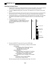
If the R reading (top display) is less than 1 mV, then proceed to the next step. If the reading is
greater than 1 mV, adjust the Voltage Input Offset pot until R is less than 1 mV.
8. Press
<Sensitivity>
Rotate the knob to select 1 mV full scale
If the R reading is less than 0.02 mV then proceed to the next step. If the reading is greater than
0.02 mV, adjust the Voltage Input Offset pot until R is less than 0.02 mV.
9. Connect the SINE OUT output to both the A and B inputs. Use equal length cables from A and B
to a BNC TEE. Connect the cable from SINE OUT to the TEE.
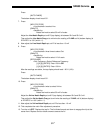
Press
[GAIN/TC]
<Sensitivity>
Rotate the knob to select 1 V full scale
[REF/PHASE]
<Ref. Frequency> Select Reference Frequency
[1] [0] [0] [ENTER] Enter 100 Hz
[INPUT/FILTERS]
<Coupling> Select DC coupling
The R reading (top display) should read 1.00 V (±2%).
Press
<Source> to select A-B
If the R reading is less than 0.001 V, then proceed to the next step. If the reading is greater than
0.001 V, adjust the Common Mode pot until R is less than 0.001 V.
Press
[GAIN/TC]
<Sensitivity>
Rotate the knob to select 2 mV full scale
If the R reading is less than 0.2 mV, then proceed to the next step. If the reading is greater than
0.2 mV, adjust the Common Mode pot until R is less than 0.02 mV.
Press
[GAIN/TC]
<Sensitivity>
Rotate the knob to select 200 µV full scale
If the R reading is less than 2 µV, then proceed to the next step. If the reading is greater than
2 µV, adjust the Common Mode pot until R is less than 2 µV.
10. The offset needs to be readjusted after adjusting the common mode. Connect a 50Ω termination
to the A input.
Press
[INPUT/FILTERS]
<Source> twice to select A
<Coupling> to select AC
[REF/PHASE]
<Ref. Frequency> Select Reference Frequency
[1] [ENTER] Enter 1 Hz


