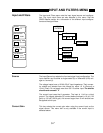
OUTPUT AND OFFSET MENU
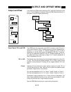
Front Panel
CH1 CH2
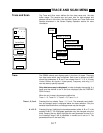
Source:
X
X Y R
Offset:
0.00%
Expand:
1
Auto:
Offset & Expand
X, Y or R Output
CH1 or CH2 Output
Offset
OUTPUT
OFFSET
Expand
Auto Offset
Source
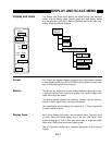
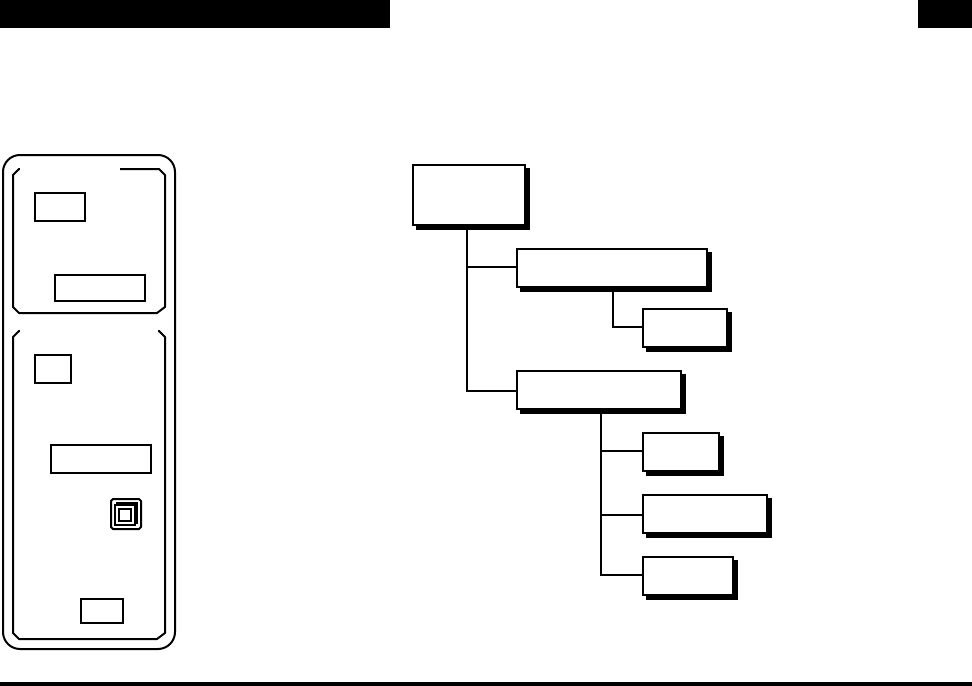
Output and Offset The Output and Offset menu selects the CH1 and CH2 outputs and sets
the X, Y and R offsets and expands. See the SR850 Basics section for a
discussion of the DC outputs and scaling.
Front Panel CH1 and CH2 The SR850 has two front panel output BNC connectors called Channel 1
(CH1) and Channel 2 (CH2). These outputs can provide voltages propor-
tional to X, Y, R, θ, or traces 1-4. Outputs proportional to X or Y have a
bandwidth of 100 kHz (the outputs are updated at 256 kHz). These out-
puts are the traditional outputs of a lock-in. Outputs proportional to R, θ,
or a data trace (even if the trace is simply X or Y) have a bandwidth of
200 Hz (updated at 512 Hz).
CH1 or CH2 The Source entry field displays the quantity being output from either CH1
or CH2. The first soft key selects whether CH1 or CH2's output source
quantity is being displayed. Pressing this key toggles between CH1 and
CH2.
Source Pressing this key selects the output source quantity for either CH1 or
CH2 as the active entry field. Use the knob to select the desired output
parameter. Keypad entry is not allowed.
CH1 can be proportional to X, R, θ, Trace1, Trace2, Trace3, or Trace 4.
CH2 can be proportional to Y, R, θ, Trace1, Trace2, Trace3, or Trace 4.
Remember, outputs proportional X or Y have 100 kHz of bandwidth. The
other output quantities should only be used if the time constant is suffi-
ciently long so there are no high frequency outputs.
See the SR850 Basics section for output scaling information.
5-15


