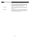
SR850 is in a remote state (front panel locked
out). The LOC indicator is on when the front panel
is active (Local Mode). The SRQ indicator is on
when the SR850 generates a service request.
SRQ stays on until a serial poll is completed.
To help find program errors, the SR850 can dis-
play the interface buffers on the screen. This
screen is activated by the View Queue function in
the Setup Communications menu. The last 256
characters received and transmitted by the SR850
are displayed.
COMMAND SYNTAX
Communications with the SR850 uses ASCII char-
acters. Commands may be in either UPPER or
lower case and may contain any number of
embedded space characters. A command to the
SR850 consists of a four character command
mnemonic, arguments if necessary, and a com-
mand terminator. The terminator must be a line-
feed <lf> or carriage return <cr> on RS232, or a
linefeed <lf> or EOI on GPIB. No command pro-
cessing occurs until a command terminator is
received. Commands function identically on GPIB
and RS232 whenever possible. Command mne-
monics beginning with an asterisk "❊" are IEEE-
488.2 (1987) defined common commands. These
commands also function identically on RS232.
Commands may require one or more parameters.
Multiple parameters are separated by commas (,).
Multiple commands may be sent on one command
line by separating them with semicolons (;). The
difference between sending several commands on
the same line and sending several independent
commands is that when a command line is parsed
and executed, the entire line is executed before
any other device action proceeds.
There is no need to wait between commands. The
SR850 has a 256 character input buffer and pro-
cesses commands in the order received. If the
buffer fills up, the SR850 will hold off handshaking
on the GPIB and attempt to hold off handshaking
on RS232. Similarly, the SR850 has a 256 charac-
ter output buffer to store outputs until the host
INTRODUCTION
The SR850 DSP Lock-in Amplifier may be remote-
ly programmed via either the RS232 or GPIB
(IEEE-488) interfaces. Any computer supporting
one of these interfaces may be used to program
the SR850. Both interfaces are receiving at all
times, however, the SR850 will send responses
only to the interface specified in the System
Setup menu (Output To RS232/GPIB function).
Use the OUTX command at the beginning of
every program to direct the responses to the
correct interface. All front panel features (except
power) may be controlled.
COMMUNICATING WITH GPIB
The SR850 supports the IEEE-488.1 (1978) inter-
face standard. It also supports the required
common commands of the IEEE-488.2 (1987)
standard. Before attempting to communicate with
the SR850 over the GPIB interface, the SR850's
device address must be set. The address is set in
the Setup GPIB menu and may be set between 0
and 30.
COMMUNICATING WITH RS232
The SR850 is configured as a DCE ( transmit on
pin 3, receive on pin 2) device and supports CTS/
DTR hardware handshaking. The CTS signal (pin
5) is an output indicating that the SR850 is ready,
while the DTR signal (pin 20) is an input that is
used to control the SR850's data transmission. If
desired, the handshake pins may be ignored and a
simple 3 wire interface (pins 2,3 and 7) may be
used. The RS232 interface baud rate, number of
data bits, and parity must be set. These are set in
the Setup RS232 menu.
STATUS INDICATORS AND QUEUES
To assist in programming, the SR850 has 5 inter-
face status indicators which are displayed at the
bottom of the screen. The RS232/GPIB Activity
indicator flashes whenever a character is received
or transmitted over either interface. The ERR indi-
cator flashes when an error, such as an illegal
command, or parameter out of range, has been
detected. The REM indicator is on whenever the
REMOTE PROGRAMMING
6-1


