5-2
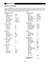
SR850 Menus
REFERENCE / PHASE
Phase 0.000°
Reference Source Internal
Reference Slope Sine
Harmonic 1
Sine Output 1.000 Vrms
Internal Frequency 1.000 kHz
Internal Sweep Linear
Sweep Start 1.0000 kHz
Sweep Stop 2.0000 kHz
INPUT / FILTERS
Source A
Current Gain 1M
Grounding Float
Coupling AC
Line Notches Out
GAIN / TC
Sensitivity 1 V
Reserve Min
Manual Reserve 3 dB
Time Constant 100 ms
Filter dB/oct. 12 dB
Synchronous Off
OUTPUT / OFFSET
CH1 Source X
CH2 Source Y
Offsets 0.00%
Expands 1
TRACE / SCAN
Trace 1 X
Trace 2 Y
Trace 3 R
Trace 4 θ
Store All Traces
Sample Rate 1 Hz
Scan Length 16000
Scan Mode Loop
DISPLAY / SCALE
Format Up/Down
Monitor Settings
Top Display Bar, Trace 1
Top Display Scale 0±1.000e0
Bottom Display Bar, Trace 2
Bottom Display Scale 0±1.000e0
Full Display Polar
Horizontal Scales 10 s/div
AUX OUTPUT
All Outputs Fixed
All Output Voltages 0.000 V
All Start Voltages 1.000 V
All Stop Voltages 2.000 V
All Offset Voltages 0.000 V
Trigger Starts No
MATH
Fit Type Line
Calc Operation x
Argument Type Trace
Argument Trace 4
Constant 0.0
SYSTEM SETUP
Output To GPIB
GPIB Address 8
Overide Remote Yes
RS232 Baud Rate 9600
Word Length 8 bits
Parity None
Key Click On
Alarms On
Plot Mode RS232
Plotter Baud Rate 9600
Plotter GPIB Address 1
Plot Speed Fast
Trace Pen 1
Grid Pen 1
Alpha Pen 1
Cursor Pen 1
Printer Type Epson
STATUS ENABLE
REGISTERS Cleared
DEFAULT SETTINGS
If the [←] (backspace) key is held down when the power is turned on, the lock-in settings will be set to the
defaults shown below rather than the settings that were in effect when the power was last turned off. The
default settings may also be recalled using the ❊RST command over the computer interface. In this case, the
communications parameters and status registers are not changed.


