4-25
FUSE
PULL
AUX OUTAUX IN
1
2
3
4 4
3
2
1
X Y
TTL OUT
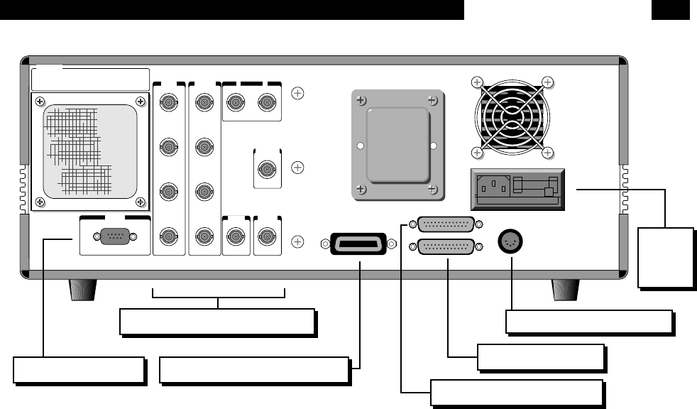
IEEE-488 STD PORT
PC KEYBOARD (8088)
PRINTER PORT
RS232 (DCE)
Fuse : 1A @100/120V & 1/2A @ 220/240V
TRIG IN
MONITOR OUT
PREAMP
STANFORD RESEARCH SYSTEMS - MADE IN U.S.A.
WARNING!:
NO USER SERVICEABLE PARTS INSIDE.
REFER TO USER MANUAL FOR SAFETY NOTICE.
FOR USE BY QUALIFIED PERSONNEL ONLY.
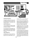
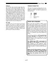
IEEE-488 (GPIB) Connector
Parallel Printer Connector
RS232 Connector
PC Keyboard Connector
Power
Entry
Module
POWER ENTRY MODULE
The power entry module is used to fuse the AC
line voltage input, select the line voltage, and
block high frequency noise from entering or exiting
the instrument. Refer to the first page of this
manual for instructions on selecting the correct
line voltage and fuse.
IEEE-488 CONNECTOR
The 24 pin IEEE-488 connector allows a computer
to control the SR850 via the IEEE-488 (GPIB)
instrument bus. The address of the instrument is
set in the SETUP GPIB menu.
Also, a GPIB plotter with HPGL compatible graph-
ics may be connected to the IEEE-488 port. In this
case, the SR850 will control the plotter to generate
plots of the screen graph. Use the SYSTEM
SETUP menu to configure the SR850 for use with
a GPIB plotter.
RS232 CONNECTOR
The RS232 interface connector is configured as a
DCE (transmit on pin 3, receive on pin 2). The
baud rate, parity, and word length are pro-
grammed from the SYSTEM SETUP menu. To
connect the SR850 to a PC serial adapter, which
is usually a DTE, use a straight thru serial cable.
Also, a serial plotter with HPGL compatible graph-
ics may be connected to the RS232 port. The
SR850 will drive the plotter to generate plots of the
screen graph. Use the SYSTEM SETUP menu to
configure the SR850 for use with a serial plotter.
PARALLEL PRINTER CONNECTOR
The [PRINT] key will print the screen to an Epson
compatible graphics printer or an HP LaserJet
compatible laser printer. Use a standard printer
cable to attach the printer to the printer port. Use
the SYSTEM SETUP menu to choose the printer.
PC KEYBOARD CONNECTOR
An IBM PC compatible keyboard may be attached
to the keyboard connector. An AT keyboard must
be in its PC or 8088 mode. Pressing ALT with a
letter on the keyboard is equivalent to pressing the
front panel key associated with that letter. (The let-
ters are shown under each key.) For example,
ALT-A is [START] and ALT-Q is [AUTO GAIN].
The function keys F1-F6 are equivalent to the six
soft keys. The right and left arrow keys function as
the knob. Keyboard number, letter and Enter keys
function normally.
Rear Panel BNC Connectors
REAR PANEL
Preamp Connector


