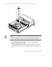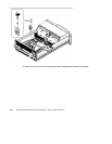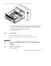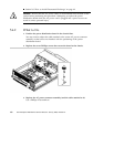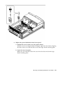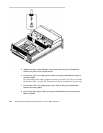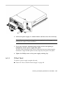
9. Connect the CPU power sense cable to the power distribution board at
connectors J0205 and J0206.
10. Connect the keyswitch/power button/LED cable to the power distribution
board at connector J0500.
11. Connect the I/O power cable to the power distribution board at connector J0210.
12. Connect the UltraSCSI data cable to the main logic board at connector J1801.
5.4.3 What Next
To reassemble the system, complete this task:
Section 6.4 “How to Replace the Fan Tray Assembly” on page 165
Section 6.2 “How to Install a Power Supply” on page 162
5.5 How to Connect the System Cables
This section provides an overview of cable connector locations and cable routing.
Procedures for removing and replacing specific cables are covered within the removal
and replacement process of the assemblies with which these cables are associated.
5.5.1 Before You Begin
Complete these tasks:
Section 2.1 “How to Power Off the System” on page 54
Section 2.4 “How to Position the System for Service” on page 60
Section 2.6 “How to Remove the System Cover” on page 65
Section 2.8 “How to Avoid Electrostatic Discharge” on page 69
5.5.2 What to Do
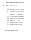
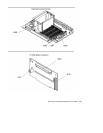
1. Identify the cable that you want to install or replace. Use the information in
the following table and illustrations to determine where to connect each end of
the cable.
Removing and Replacing Backplanes and Cables 155


