


Create Corner Frames (Create)
183
Create Corner Frames (Create)
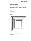
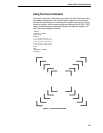
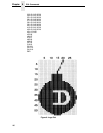
This command allows you to crate Corner Frames for your forms. Similar to
the BOX command, you define starting and ending points but in addition, you
specify the length of the horizontal and vertical arms of each corner frame.
The basic command for creating Corner Frames is:
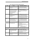
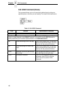
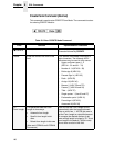
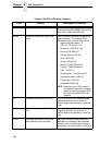
Table 22. Corner Command
Field Function Option/Modifier Selections
CORNER This is the command specifier.
Using the following parameters
creates a set of corners around a
specified area of the form at a
specific line thickness and length of
vertical and horizontal arms of
each corner.
Enter CORNER
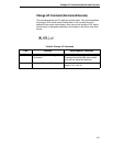
LT; Dictates the line thickness. Line thickness is based on dot increments
(1/72”) horizontally and vertically. Line
thickness is only limited by your
specifications. Do not forget the parameter
delimiter.
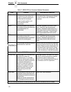
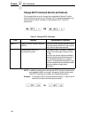
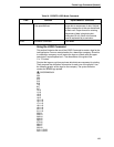
The SR, SC, ER, and EC parameters use the same methods for defining the CORNER Print area.
Whether in columns or dots depends on the SCALE Command. You may also use the XX.YY
format for plotting duplication print locations explained earlier in the Standards Section.
SR; Plots the starting ROW of the
corner.
Enter a value ranging from 1 to one less
than the maximum form length and the
parameter delimiter.
SC; Plots the starting COLUMN of the
corner.
Enter a value ranging from 1 to one less
than the maximum form width and the
parameter delimiter.
ER; Plots the ending ROW of the
corner.
Enter a range ranging from 2 to one less
than the maximum form length and the
parameter delimiter.
EC Plots the ending COLUMN of the
corner.
Enter a value ranging from 2 to one less
than the maximum form width.
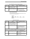
The VL and HL parameters specify the arm length of each corner piece in dots or characters
depending on the SCALE Command. You may also use the XX.YY format.