


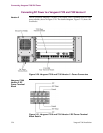

Vanguard 7300 Installation 3-29
Cabling Procedures
CPU Cards
There are two types of Central Processor Unit (CPU) cards that are supported in the
Vanguard 7300 Series Platform.
• MPC750
• IBM750FX
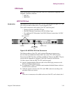
MPC750 CPU Card
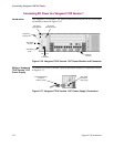
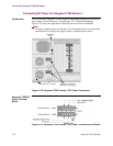
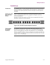
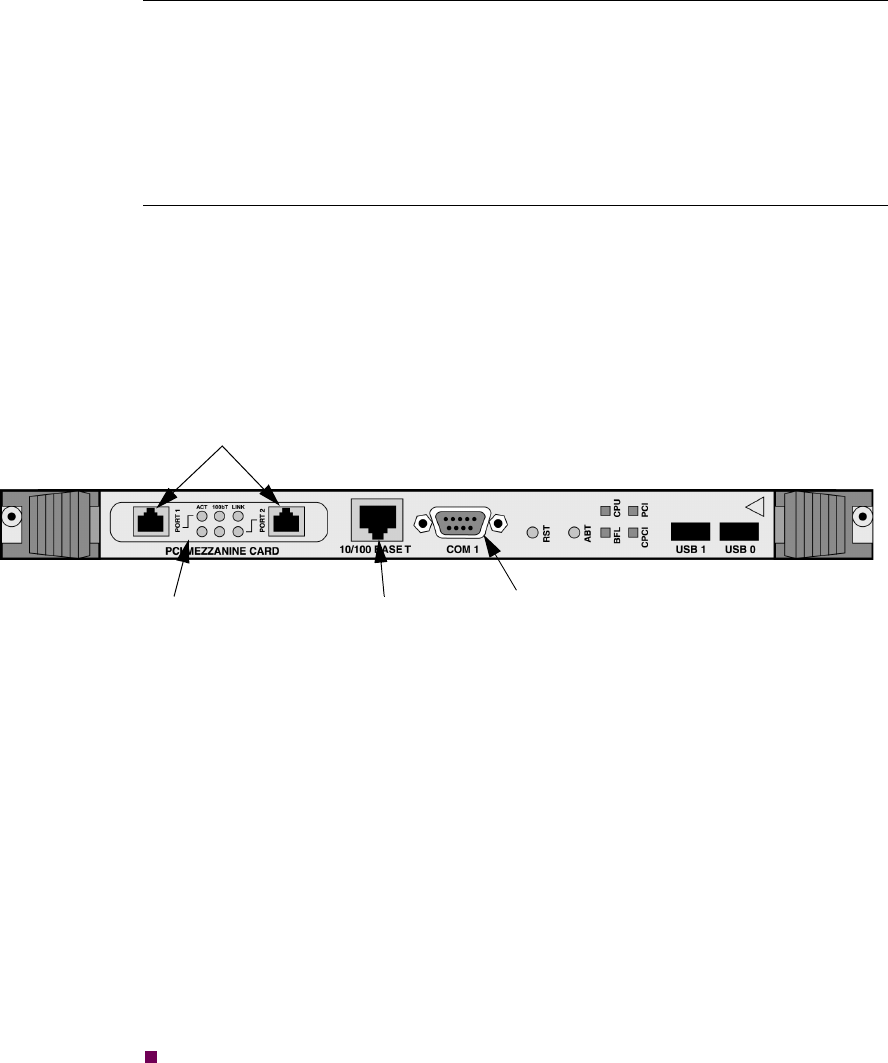
Introduction The connectors on the front of the MPC750 CPU card are show in Figure 3-22. The
CPU always resides in chassis slot 1 of your Vanguard 7300.
These cable connections can be made to the CPU card front panel:
• Operator Console to the DB9 CTP port
• One RJ45 Ethernet Connection to the 10/100 BaseT port
• Two additional PCI Mezzanine Card (PMC) Ethernet connections, if a PMC
is installed
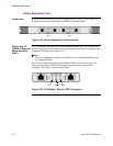
Figure 3-22. MPC750 CPU Card Connectors
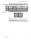
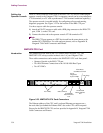
The Ethernet address of the CPU card’s on-board Ethernet port appears on a
bar-code label just behind the Ethernet PMC slot on the CPU card front panel.
Pinouts for the MPC750 CPU card RJ45 10/100BaseT Ethernet and DB9 CTP ports
are provided in Appendix B, Vanguard 7300 Cable Connectors and Pinouts.
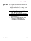
Use these steps to cable the MPC750 CPU card front panel:
1) Attach a standard shielded Ethernet cable with an RJ45 plug connector to the
RJ45 10/100 BaseT Ethernet port.
2) If an Ethernet PCI PMC is installed, attach standard shielded Ethernet cables to
the RJ45 socket connectors.
3) Cable the operator console to the CPU card’s DB9 connector according to the
procedure in the next section.
Note
There are no connectors to be cabled at the rear of the CPU card’s chassis slot 1.
PMC Connectors
PCI PMC
RJ45 10/100
BaseT Ethernet
Port
DB9 CTP Port