


Modifying Your Vanguard 7300 5-25
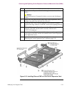
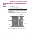
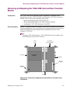
Removing and Replacing the T1/E1/PRI Card and Rear Transition Module
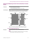
Removing and Replacing the T1/E1/PRI Rear Transition Module
Introduction The T1/E1/PRI Rear Transition Module provides physical connector interfaces for
T1/E1/PRI card data and voice functions.
Note
Review all applicable warnings and cautions in the “Hot-Swapping Cards and
Modules” section on page 5-2 before you begin.
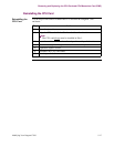
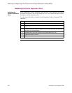
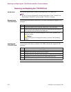
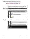
Removing the T1/
E1/PRI Rear
Transition Module
Use the steps in this table to remove a T1/E1/PRI Rear Transition Module from the
Vanguard 7300 enclosure:
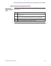
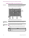
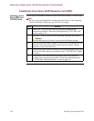
Installing the
T1/E1/PRI Rear
Transition Module
Use the steps in this table to install the T1/E1/PRI Rear Transition Module into the
Vanguard 7300 enclosure:
Step Action
1 Disconnect any cables attached to the module’s connectors.
2 Loosen the captive screws on the T1/E/1/PRI Transition Module at the rear
of the Vanguard 7300.
3 To eject the T1/E1/PRI Transition Module, press the two ejector lock
buttons and then press the card’s levers outward at the same time.
4 Carefully slide the T1/E1/PRI Rear Transition Module out of its card rails
and place it on a level surface.
Step Action
1 If applicable, remove the rear chassis cover to access the midplane of the
Vanguard 7300.
2 Open the ejector levers on the T1/E1/PRI Rear Transition Module.
3 Locate the correct slot; the T1/E1/PRI Rear Transition Module should be
installed from the rear in the same slot as the T1/E1/PRI Card.
Align the T1/E1/PRI Card with the card rails on the Vanguard 7300 chassis.
4 Carefully insert the T1/E1/PRI Rear Transition Module in the card rails and
slide the card until you feel resistance.
5 Simultaneously press the ejector levers inward until they lock.
6 Tighten the captive screws.
7 Reconnect any connector cables.