


Vanguard 7300 Enclosures and Components 2-15
Vanguard 7300 Cards
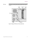
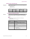
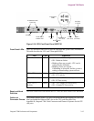
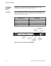
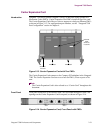
Figure 2-10. CPU Card Front Panel, MPC750
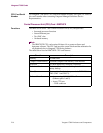
Front Panel LEDs The CPU card offers four LEDs to provide operation and system status information.
This table describes the CPU card’s front panel LEDs:
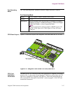
Reset and Abort
Switches
The Reset switch resets and restarts the CPU card; the Abort switch is not functional.
Cable and
Connector Pinouts
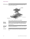
The Ethernet address of the CPU card’s on-board Ethernet port appears on a bar-code
label just behind the Ethernet PMC slot on the CPU card front panel. See
Appendix B, Vanguard 7300 Cable Connectors and Pinouts for pinouts for the CPU
card ports.
Front Panel
LEDs
PCI PMC
10/100 BaseT
Ethernet Port
DB9 CTP
Port
Reset Switch
Abort Switch
(not used)
USB 1
(not used)
USB 0
(not used)
Serial No.
Location
10/100 BaseT PMC
Connectors
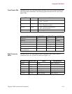
LED Color Indication
BFL - Board Failure Yellow • OFF - Normal CPU card operation
• ON - Hardware failure
• Blinking (Once per second) - CPU card is
waiting for the coldloader
• Blinking (Twice per second) -
Coldloading is successful, and the system is
waiting or downloading system software
CPU - CPU Activity Green • OFF - No CPU activity
• ON - CPU activity
PCI - PCI Activity Green • OFF - No local PCI bus activity
• ON - PCI bus activity
CPCI - CPCI
Activity
Green • OFF - No Compact PCI bus activity
• ON - Compact PCI bus activity