


4-2 Operating Your Vanguard 7300
Power-Up Procedure
Power-Up Procedure
Introduction This section explains how to power-up a Vanguard 7300 Series router. To power
down your Vanguard 7300, set the power switch to the off position.
Note
Before you begin, be sure to review all applicable warnings and cautions in the
“Electrostatic Discharge Precautions” section on page 3-7.
Power-Up
Instructions
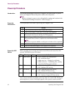
Use the procedure in this table to power-up your Vanguard 7300:
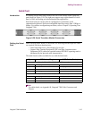
Power-Up LED
Values
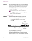
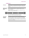
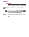
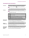
When you apply power, the fan starts and the four LEDs on the front of the CPU
activate. This table lists the LED values:
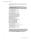
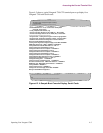
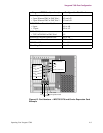
Next, each pre-installed card displays power-up status on its own LEDs. During the
power-up process, a series of messages appears on the operator console terminal.
Step Action
1 Check that all the cards are fully inserted and secured.
2 Check that all empty or open slots are covered with slot panels.
3 Make sure the AC power cord(s) are plugged in. For all Vanguard 7300
DC powered units, be sure that they are wired properly.
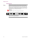
4 Flip the Vanguard 7300 AC or DC power switches to the on position. For
DC powered units (Version 1) depress the circuit breaker switch.
Note
If you have two power modules, set the power switches to the on position.
5 Check that the fan(s) operate correctly.
6
Check the front panel displays for the proper LED sequences.
LED Meaning Color Indication
BFL Board Failure Yellow • OFF - Normal CPU card operation
• ON - Hardware failure
• Blinks once/sec. - Waiting for cold loader
• Blinks twice/sec. - Coldloading done, waiting
for or downloading system software
CPU CPU Activity Green • OFF - Indicates no CPU activity
• ON - Indicates CPU activity
PCI PCI Activity Green • OFF - Indicates no PCI bus activity
• ON - Indicates PCI bus activity
CPCI CPCI Activity Green • OFF - Indicates no Compact PCI bus activity
• ON - Indicates Compact PCI bus activity