


Modifying Your Vanguard 7300 5-5
General Card Replacement Guidelines
Inserting a
CompactPCI Card
or Transition
Module
Whether you are replacing an existing CompactPCI component or adding a new
component to your Vanguard 7300, care must be taken when inserting a component’s
midplane socket (female) connectors over the rows of male pin connectors on the
CompactPCI midplane. Before replacing or adding a Vanguard 7300 card or
transition module, be sure to familiarize yourself with CompactPCI midplane chassis
design. Compact PCI card and transition module descriptions and connector
characteristics are illustrated in the “Vanguard 7300 Platform Version 1” section in
Chapter 1.
The pin connectors that line the front and rear of the CompactPCI midplane must not
be damaged; a single bent pin can prevent a card from seating properly and could
even disable an entire chassis. Although Vanguard 7300 chassis are equipped with
card guides and other alignment mechanisms to minimize the possibility of damage,
inserting components requires careful handling.
Before You Begin... Use the procedure in this table to insert cards and rear transition modules into a
Vanguard 7300 chassis:
• For your personal safety, be sure to review all of the preceding safety
warnings and cautions before you begin to replace any Vanguard 7300
component
• Be sure to use a grounded wrist strap, static-dissipating work surfaces, and
anti-static bags for component storage
• Unscrew and remove the slot cover from the chassis slot. Slot covers should
be stored for reuse in case the card is removed in the future
Step Action
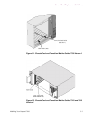
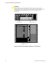
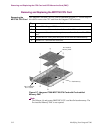
1 Align the card with the card guides in the chassis slot. Be sure both ejection
levers are in the open position. (Refer to Figure 5-4.)
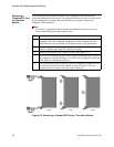
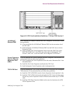
2 Insert the card into the card guides and slide the card into the chassis until
you feel resistance (approximately 1/4 inch short of full insertion). Use
even pressure and do not rock or force the card to insert it.
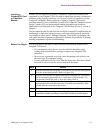
3 Simultaneously press both ejection levers inwardly toward the center of the
card until the levers lock into their slots. The front panel should be flush
with the adjacent cards and/or slot covers.
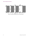
4 Tighten the captive screws on the card or transition module to secure it.
5 Install port cables according to the cabling directions for the specific card
or transition module according to instructions further on in this chapter.