


About Vanguard 7300 1-19
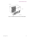
Vanguard 7300 Platform Version 2
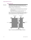
CompactPCI Connectors
Description The CompactPCI midplane is located toward the middle of the chassis, and each card
slot is equipped with male J1 connectors (pins). The plug-in cards use socket
(female) connectors. The same type of connectors are used on the rear side of the
midplane to accept rear I/O transition modules. Midplane connectors have external
metal shields for proper shielding and grounding in noisy environments. Controlled
impedance minimizes unwanted signal reflections.
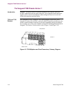
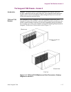
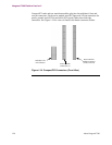
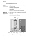
Figure 1-13 shows the standard five CompactPCI card connectors that make up the
CompactPCI bus interface and the user input/output sub-bus. The following table
summarizes the function of the standard card connectors:
Figure 1-13. CompactPCI Bus Connectors (Side View)
Bus Type Connector Purpose
CompactPCI
Bus
J1 32-bit CompactPCI connector
J2 64-bit CompactPCI connector
User I/O
Bus
J3 I/O Signal Distribution
J4 H.110 bus access
J5 External I/O (Telephony) access
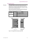
Compact PCI Card
Shielded Compact
PCI Rear Transition
Module
6U
User I/O
or
Sub-Bus
Telephony
I/O
Compact
PCI Bus