


B-7
Serial Card Connector and Cable Details
Serial Card Connector and Cable Details
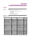
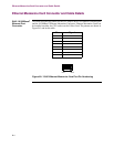
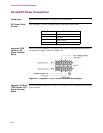
Introduction This section describes the details of the serial card connector and cable.
Cable Connector The following cable connector information applies to the Vanguard 7300 Serial
Card. Pinouts for the exterior interface end of these Serial Card cables are in the
following subsections:
• EIA 232 DCE
• EIA 232 DTE
• V.35/V.36 DCE
• V.35/V.36 DTE
• X.21 DCE
•X.21 DTE
• EIA 530 DCE
• EIA 530 DTE
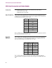
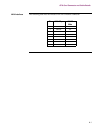
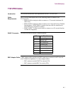
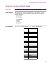
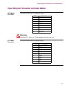
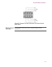
EIA 232 DCE/DTE This is a list of the Serial Card EIA 232 DCE and DTE connector pinouts:
Pin Signal
1Prot Gnd
2TD
3RD
4RTS
5CTS
6DSR
7 Signal Comm
8 DCD
9(not used)
10 (not used)
11 (not used)
12 (not used)
13 (not used)
14 (not used)
15 TXC
16 (not used)
17 RXC
18 (not used)
19 (not used)
20 DTR
21 (not used)
22 RI (DCE Out)
23 (not used)