


5-14 Modifying Your Vanguard 7300
Removing and Replacing the CPU Card and CPU Mezzanine Card (PMC)
Installing an
Ethernet PMC on
the MPC750 CPU
Card
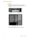
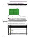
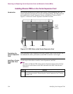
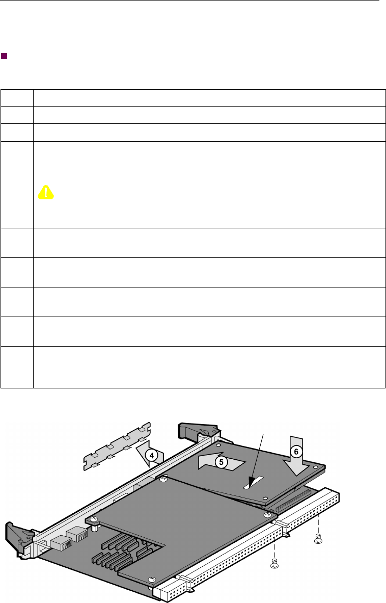
To add a 10/100BaseT Ethernet PMC, install the first PMC in the MPC750 CPU
Card PCI PMC location beside the Memory PMC. Use the steps in this table to
install the Ethernet PMC on the CPU Card:
Note
To remove a 10/100BaseT Ethernet PMC, reverse steps 4-6 in this table:
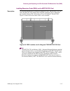
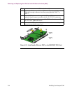
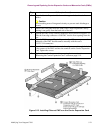
Figure 5-9. Installing the Ethernet PMC on the MPC750 CPU Card
Step Action
1 Turn off power to the Vanguard 7300.
2 Disconnect any cables attached to the front of the MPC750 CPU card.
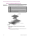
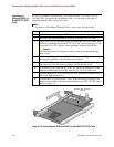
3 Remove the CPU card from the enclosure according to the instructions in the
“Removing and Replacing the MPC750 CPU Card” section on page 5-12. Be
sure to place the CPU card on a clean, grounded, and static-free surface.
Caution
Avoid touching areas of integrated circuitry; static discharge can damage
these circuits.
4 Remove the filler panel from the PCI PMC location on the front of the CPU
card by gently pushing it out from the back of the rail.
5 Position the PMC on top of the card as shown in Figure 5-9. Slide the front
edge connectors into the opening labelled “PCI Mezzanine Card”.
6 Press the PMC down onto the top of the CPU card. The connectors on the
underside should connect smoothly with the J11/12/13/14 connectors.
7 Insert the short screws at the corners of the PMC and into the standoffs on the
CPU Card. Tighten the screws.
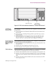
8 Re-install the CPU card into PMC slot 1 on the enclosure according to the
instructions provided in “Removing and Replacing the MPC750 CPU Card”
section on page 5-12.
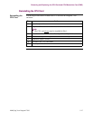
Ethernet PMC Serial No.
Location