


Replacing Power Supplies and Cooling Fans 6-3
Replacing Power Supplies and Cooling Fans, 7310 Version 1
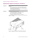
Removing and Installing the Power Supply/Inlet Fan Module
Introduction This section explains how to install and remove the Power Supply/Inlet Fan Module
from both AC and DC-powered Vanguard 7310 routers.
Note
Be sure to review all applicable warnings and cautions in the “Hot-Swapping
Cards and Modules” section on page 5-2 before you begin. The power supply is
not hot-swappable on the Vanguard 7310 Version 1.
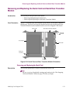
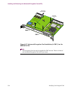
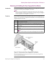
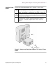
Procedure Refer to Figure 6-4 and the steps in this table to remove the Power Supply and Fan
Module. To re-install the Power Supply/Inlet Fan Module, reverse this procedure and
reconnect the power to the unit.
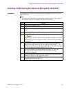
Figure 6-2. Removing the Power Supply/Inlet Fan Module
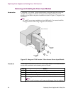
The Inlet Fan Module can be disconnected from the unit by unscrewing the four
screws on the front of the unit.
Step Action
1 Turn off power to the unit.
2 Disconnect the AC power cord or the DC connections from the unit.
3 Unscrew and remove the front cover for access to the power supply/inlet
fan module.
4 Remove the single captive screw on the lower front corner of the
module.
5 Carefully pull on the module to slide it out of the front of the chassis.
Note
There is initial resistance until connectors disengage from the midplane.
Power Supply/Inlet Fan
Module
Inlet Fan
Module
Module
Handle
Front of Chassis