


Vanguard 7300 Installation 3-35
Cabling Procedures
Serial Card
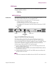
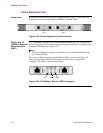
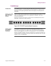
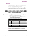
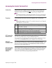
Introduction All cabling for the Serial card is done at the rear of the chassis on the 8-port rear
panel shown in Figure 3-28. The eight ports support up to eight channels of serial
data for WAN networking and telecommunications applications.
Each Serial card port can be software configured for synchronous serial
communication protocol. Software-configurable baud rates range from 1.2Kbps to
8Mbps. For software configuration procedures, refer to Chapter 4, Operating Your
Vanguard 7300.
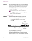
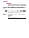
Figure 3-28. Serial Transition Module Connectors
Cabling the Serial
Card
Due to the high traffic density of this board, the following interface-specific cables
are required with these characteristics:
• Serial card cables have a fixed length of seven feet
• Separate Data Terminal Equipment (DTE) and Data Communications
Equipment (DCE) cables are required because DTE/DCE operating mode is
determined by the physical cable characteristics
This table lists the cables available for use with the Serial card:
Note
For cable details, see Appendix B, Vanguard 7300 Cable Connectors and
Pinouts.
Type DTE Cable (Plug) DCE Cable (Socket)
Standard Serial Card Cables (English screws)
EIA232 DB25 (plug J-screw-Male) DB25 (socket screwlock-Female)
EIA232 ---------- DB25 (plug J-screw)
V35/V36 M34 M34
X21 DB15 (plug J-screw-Male) DB15 (socket screwlock-Female)
Standard Serial Card Cables (Metric screws)
EIA232 DB25 (plug J-screw-Male) DB25 (socket screwlock-Female)
EIA232 ---------- DB25 (plug J-screw-Male)
EIA530 DB25 DB25