


Vanguard 7300 Installation 3-11
Removing And Replacing Vanguard 7300 Front Covers
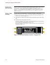
The Vanguard 7310
Version 1 Front
Cable Channel
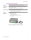
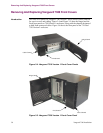
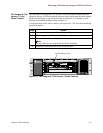
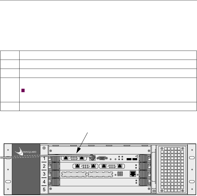
The left-hand fixed Vanguard 7310 Version 1 front cover panel contains the cable
channel at the top. All front-connected interface cables run through the cable channel
behind the fixed panel to exit on the left side of the chassis. For example, see the
location of the shielded Ethernet cable in Figure 3-7.
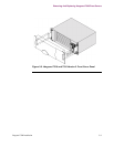
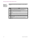
Use the procedure in this table to remove and replace the 7310 fixed front panel and
position the cables:
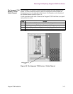
Figure 3-7. The Vanguard 7310 Version 1 Cable Channel
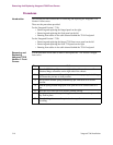
Step Action
1 Remove the two nuts that hold the left panel to free it.
2 Place the panel on a flat level surface, painted side up.
3 Gather all front cables and align them neatly in the cable channel.
Note
Be sure cables are not tangled and are clearly identified.
4 Replace the front panel and secure it with the nuts.
PORT 1
PORT 2
ACT100bTLINK
PORT 1
PORT 2
ACT100bTLINK
EXTPWR
ABT
RST
BFL
CPCI
USB 1COM 110/100 BASE T USB 0
CPU
PCI
PCI MEZZANINE CARD
PORT 1
PORT 2
ACT100bTLINK
P
M
C
2
D
E
B
U
G
HOT SWAP
RESET
P
M
C
1
11
7
3
8
W
A
N
4
0
Universal
Serial I/O
EXT PWR
Shielded Ethernet Cable