9-2 CHAPTER 9: SETTING UP THE SYSTEM FOR ROVING ANALYSIS
the remote port is located. The remote system must be located on the same
FDDI ring as the system to which the analyzer is attached.
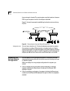
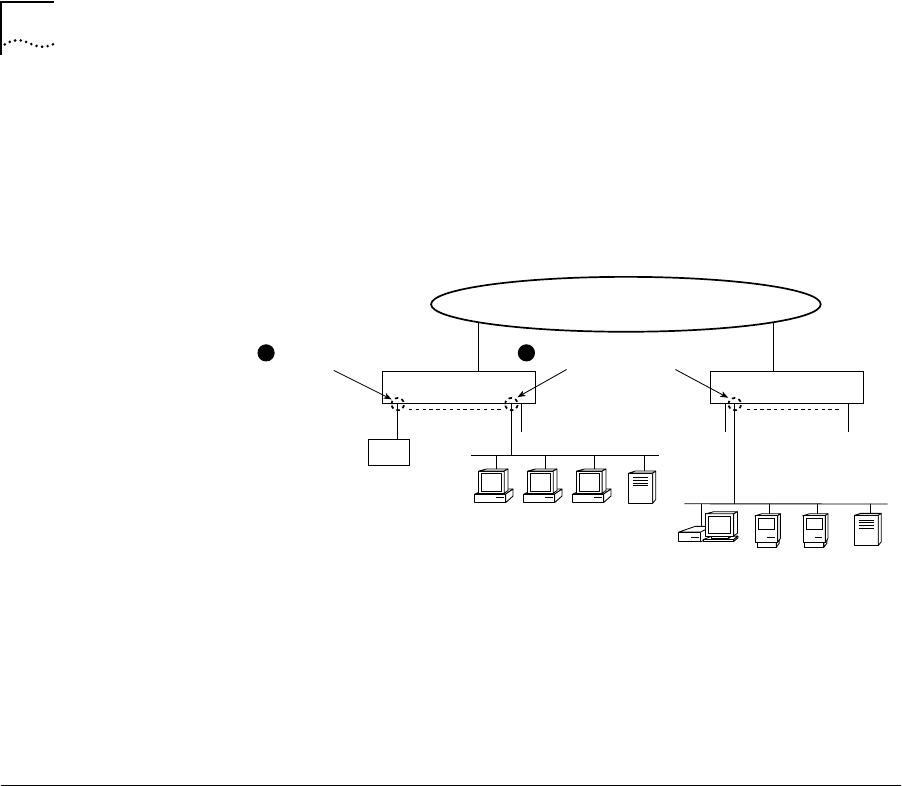
Figure 9-1 shows the process for establishing local and remote monitoring
of ports.
Figure 9-1 Roving Analysis of Local and Remote Ethernet Ports
Configuration rules You can have a maximum of 16 network analyzers connected to a system
(the maximum number of Ethernet ports on a system) and up to 8 ports
monitored per system. The network analyzer cannot be located on the same
segment as the port you want to monitor. In general, you will configure one
analyzer port ➊ and from there monitor one Ethernet port at a time ❷.
Displaying the
Roving Analysis
Configuration
You can display the roving analysis configuration to see which ports are
designated as analyzer ports and which ports are currently being monitored
on a specific system.
When you display the roving analysis configurations for a system, you
receive:
■ A list of analyzer ports on the system (ports connected to a network
analyzer), including the Ethernet port number and the Ethernet MAC
address of the port
■ A list of ports being monitored on the system, including the Ethernet port
number and the Ethernet MAC address of the port to which the analyzer is
attached
Switch 2200 Switch 2200
Ethernet ports Ethernet ports
Local port
to monitor
Remote port
to monitor
OR
Network Analyzer
Port chosen for
network analyzer
1
2
FDDI


