


102 CHAPTER 3: MULTIFUNCTIONAL INTERFACE MODULES
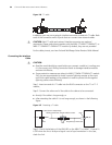
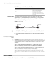
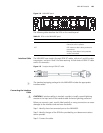
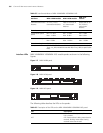
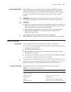
Interface LEDs The following figure illustrates the MIM-4BSE panel.
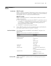
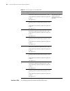
Table 61 Set the jumpers on the MIM-4BSE
Jumper settings & description Default
Interface
0
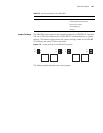
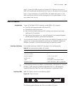
S2 To use a 100-ohm matched resistance for data
transmission, place the jumper over pins 1 and 2.
To do otherwise, place the jumper over jump pins
2 and 3.
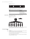
See Figure 113.
The jumpers are placed
over jump pins 2 and 3,
meaning 100-ohm
matched resistances are
not used.
S1 To use a 100-ohm matched resistance for data
receiving, place the jumper over jump pins 1 and
2.
To do otherwise, place the jumper over jump pins
2 and 3.
See Figure 113.
Interface
1
S4 To use a 100-ohm matched resistance for data
transmission, place the jumper over pins 1 and 2.
To do otherwise, place the jumper over jump pins
2 and 3.
See Figure 113.
S3 To use a 100-ohm matched resistance for data
receiving, place the jumper over jump pins 1 and
2.
To do otherwise, place the jumper over jump pins
2 and 3.
See Figure 113.
Interface
2
S6 To use a 100-ohm matched resistance for data
transmission, place the jumper over pins 1 and 2.
To do otherwise, place the jumper over jump pins
2 and 3.
See Figure 113.
S5 To use a 100-ohm matched resistance for data
receiving, place the jumper over jump pins 1 and
2.
To do otherwise, place the jumper over jump pins
2 and 3.
See Figure 113.
Interface
3
S8 To use a 100-ohm matched resistance for data
transmission, place the jumper over pins 1 and 2.
To do otherwise, place the jumper over jump pins
2 and 3.
See Figure 113.
S7 To use a 100-ohm matched resistance for data
receiving, place the jumper over jump pins 1 and
2.
To do otherwise, place the jumper over jump pins
2 and 3.
See Figure 113.